

Drawings and documents
National Archives restored drawings: drawing
A. Turney's Patent Drawing for a Machine for Boring Stones for Blasting

National Archives, Restored Patent Drawings (Record Group 241) · Full-size scan at the National Archives · Catalog record
Show the text on the drawing Hide (49 words)
Words on the drawing as machine-read by the National Archives; not checked. Useful mainly for searching.
125 ARTESIAN & OIL WELLS / A. TURNEY'S / Reamers. / DIV. 15 / Machine for boring Stones for Tolasting. / fist / classification / Patented March 30*/1336. / 9555) / DIVISION / 9555X / 7. / Fig. 6. / Fig.5. / (y / my 8 / 13 / II / by / Fig: 4. / To / OR / It / Hig. 3. / Fig.,
USPTO scan
The patent as scanned by the USPTO
-
 Page 1
-
 Page 2
-
 Page 3
-
 Page 4


U.S. Patent and Trademark Office · Google Patents
Show the transcription Hide (1,052 words)
Machine transcription (LightOnOCR) of the pages as scanned by the USPTO, most of them the handwritten copies made when the records were restored after the 1836 fire. Not checked; it can misread handwriting, so compare it with the scan.
Page 1.
9555X
A. Turney,
Expanding Rock Drill.
Patented Mar. 30, 1836
NO PRINTED COPY OF SPECIFICATION IN OFFICE.
Fig. 1.
Fig. 2.
Fig. 3.
Fig. 4.
Fig. 5.
Fig. 6.
Fig. 7.
Fig. 8.
Page 2.
No. 15.
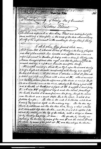
Andrew Turney, of Reading, State of Connecticut.
Letters Patent.
The scheme referred to in these Letters Patent and making part of the same, containing a description in the words of the said Andrew Turney himself of his improvement in the machine for boring stone for blasting.
To all to whom these presents shall come,
Be it known that I, Andrew Turney of Reading in the County of Fairfield and State of Connecticut, have invented and applied to use a new and useful improvement or Machine for boring rocks or stone for blasting, and Andrew Turney in process stone says, and that the following "with the annexed drawings is a full and accurate description thereof."
This invention consists of a Shank C, in Fig 1, upon the annexed drawing, to be of a length and diameter corresponding with the size and depth of the hole to be bored. To this Shank is attached a chisel D3 fitted with a lock and joint, and fastened with a screw at M, other at convenient and suitable distance from the opposite end of the Shank is a screw D, fitted so as to revolve around the Shank, extending to B, having a joint at B and a handle at G and foot is fixed at H to support a small pulley I. A cord FE of sufficient size to work the chisel, passing through the handle to which it is made fast, over the pulley, through the screw near the Shank and a small staple L, to the chisel, to which it is fastened by a pin. The hole in the rock to be blasted is to be bored to nearly the required depth in the ordinary way. Then the stone says should be introduced into the hole thus bored, having a chisel attached to it, somewhat less than the hole, and the force is to be applied to the chisel by striking on the top of the Shank, with a sledge or hammer or by elevating and forcing it down. The operator, by elevating and depressing the handle, by means of the cord F and the screw D works the chisel by means of the joint at M, and thus enlarges the chamber.
Page 3.
362. 9555X 358-1836
1. At the bottom of the hole, for the reception of the charge to any required dimension, a set of chisels, figures 2. A., of different lengths and sizes and having edges of different degrees of obliquity to the shank should be prepared, and in reading so that the size of the chamber for the reception of the charge may be graduated and inequalities in the bottom of it, to a greater extent, cut off.
And, if necessary, a double set of chisels, figures 3. 4. B., H., may be fitted in with cords, attached thereto in the same manner as has been already described in the case of the chisel B., these cords to pass up on both sides of the shank over the fulcrum, and to be fastened to the handle, so that by elevating and depressing the handle, the two chisels will be made to strike in opposite directions, and thus cut faster and smoother than with a single one. Or the chisel may be fastened to the shank having a joint but without a screw, as in figure 9.
When the work with these chisels is completed, the bottom of the chamber will still be uneven. A tool, a scraper E, figure 5 with a stone G, may then be introduced. The shanks of this scraper should be so bent near the bottom, and the edge of the chisel so arranged, that the chisel, when introduced, will, upon being turned, cut that part of the chamber which could not be reached by a common stone scraper. The scraping should be on the opposite side of the shank to the sharpest angle of the chisel, and extend downwards, so that the part G will hold the chisel to its place, and extend the extreme point of the chisel into the chamber. The dust is removed from the chamber by a scraper E, figure 6, consisting of a straight rod with a spoon C, of a suitable size, attached to the lower end with a joint H, and wire G is fastened to the spoon, and passes through a staple at K.
After the scraper is introduced into the chamber the operator by putting the cord and moving the rod, can reach and clean every part of the chamber.
When there is water in the hole the charge is introduced in the following manner: A sack is prepared of leather, india rubber, or any other suitable material, impervious to water, corresponding in shape with the size of the hole and the chamber. Figure 8 so that the bottom of the sack when filled with powder, will fill the chamber. In this sack is inserted a tin, or other thin metallic tube extending downwards to the point where the sack begins to enlarge. This sack and tube are then introduced into the hole, and charge
Page 4.
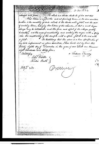
charged with powder. The cheeks and cheeks should be of iron and cast
What I claim as my invention and not previously known, in the above described machine is the connecting of said cheeks to the cheeks with a joint, and the mode of working them, enlarging the bottom of the chamber, so that a much larger charge may be introduced, and the force and effect of the charge, greatly increased, and the mode of constructing and working the auger with a spring also the constructing of the scraper with a spring, fitted to the rod with a joint.
In testimony that the above is a true specification of my said improvement as above described, I have hereunto set my hand this twenty-eighth day of December in the year of our Lord one thousand eight-hundred-and-thirty-six.
Witness
John Dibble
Robin Booth
1095
Drawing
C. Hudson & Co.
Published accounts: journal notice
Notice in the monthly list of patents
Journal of the Franklin Institute, new ser., vol. 17 (1836), p. 439 · View the page
235. Boring stones. Andrew Turney, Reading, Conn.
About this record
- Patentee
- DATAMP
- Date
- the Name and Date index of patents, DATAMP, USPTO records
- Invention
- DATAMP
- Listed in
- the Name and Date index of patents, DATAMP, USPTO records, Jim Shaw's X-patent list, the Journal of the Franklin Institute