

Drawings and documents
National Archives restored drawings: drawing
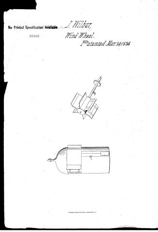
Job Wilbur's Patent Drawing for a Windmill

National Archives, Restored Patent Drawings (Record Group 241) · Full-size scan at the National Archives · Catalog record
Show the text on the drawing Hide (18 words)
Words on the drawing as machine-read by the National Archives; not checked. Useful mainly for searching.
OIR / se
USPTO scan
The patent as scanned by the USPTO
-
 Page 1
-
 Page 2
-
 Page 3


U.S. Patent and Trademark Office · Google Patents
Show the transcription Hide (821 words)
Machine transcription (LightOnOCR) of the pages as scanned by the USPTO, most of them the handwritten copies made when the records were restored after the 1836 fire. Not checked; it can misread handwriting, so compare it with the scan.
Page 1.
No Printed Specification Available
9556X
J. Wilbur,
Wind Wheel.
Patented Mar. 30, 1836


Page 2.
9556X
Mar 30, 1836
No. 14
1/2
Job Wilbur.
of Fall River, Mass. of Massachusetts.
Letters Patent.
The schedule referred to in these Letters Patent and making part of the same containing a description in the words of the said Job Wilbur himself of his "Improvement in the Wind Mill."
To all to whom these presents shall come.
Be it known that I Job Wilbur of Fall River, in the County of Bristol, and Commonwealth of Massachusetts, do hereby declare that I have invented a new and useful improvement in Wind Mills, or the application of Wind power. Called Wilbur's Patent Wind Mill, and that the following is a full and exact description of the construction and operation of the said machine, as invented or improved by me.
It consists of two general parts to wit the building and the machinery, one of the building is to be round, thirty feet in height, and twenty feet in diameter; and constructed in two parts. The first part is stationary, and is to be erected on a solid foundation, twenty feet high, having a strong plate at the top, well studded. The second part of the building is ten feet in height from the top of the plate of the first part, and is movable, having a roof firmly framed or fastened to the top and fitting over about six inches; the base of the movable part is fitted to move on a rail way, on the plate of the stationary part, and is moved to receive the wind, by means of a tackle and pulley, the block being hooked to the movable part and moved from hook to hook, as occasion may require, to bring the wheel properly to the wind. In the side of the movable part is a window six feet wide and ten feet high, having a shutter fitted to the shape of the building, for the purpose of admitting the wind upon the wheel, having the shutter so fixed as to remain immovable by the wind in any extent of opening desired. Opposite to this window, is a like window for the purpose of discharging the wind, the situation of these windows is such as that a line drawn from the inner edge of one to the other, parallel
Page 3.
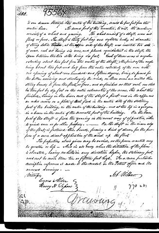
to one drawn through the centre of the building, would be some feet from the centre line.
The second part of this invention, to wit: the machinery consists of a wheel and gearing. The wheel consists of a shaft, arms and floats or fans. The shaft is thirty feet long and eighteen inches in diameter of strong solid timber, at the upper end of this shaft, are inserted two sets of arms, each set having six arms, and placed equidistant in the shaft, the space between the two sets being six feet. Each of these arms is angular extending about two feet from the centre of the shaft; the point of the angle being about two feet and half from the outer extremity of the arm with one opening of about one hundred and fifteen degrees, being so formed for the better receiving and discharging the wind, on these arms are nailed thin strong boards to form the floats, or fans, and so finished as that each one shall be two feet by six feet on the outer extremities of the arms. This wheel thus finished, having in the lower end of the shaft a pivot, and in the upper end an arbor moves on a plate of steel fixed in the centre side of the stationary part of the building, in the centre of the building, and at the top in a quaggon in a beam in the centre of the movable part of the building. On the lower part of the shaft is fixed the gearing in the usual way of operation, either to grind corn or for other purposes. On the shaft in the inner edge of the float, is fastened thin boards, forming a kind of drum, for the purpose of a more direct application of the wind up the float.
The properties above given may be varied, as the power wanted may be greater or less — and in all cases where the situation of the place is elevated, having no hills in any direction higher, the stationary part need not be more than ten or fifteen feet high. For a more particular description reference is made to the model in the Patent office and the annexed drawings.
Witness
Gypen Alder
Harry H. Clapton
Lot Milburn
770 w7
Drawing
About this record
- Patentee
- DATAMP
- Date
- the Name and Date index of patents, DATAMP, USPTO records
- Invention
- DATAMP
- Listed in
- the Name and Date index of patents, DATAMP, USPTO records, Jim Shaw's X-patent list, Burke's List of Patents (1847)
- Burke's 1847 Patent Office list gives the same patent.