

Drawings and documents
National Archives restored drawings: drawing
A. W. Gray's Patent Drawing for a Corn Sheller

National Archives, Restored Patent Drawings (Record Group 241) · Full-size scan at the National Archives · Catalog record
Show the text on the drawing Hide (38 words)
Words on the drawing as machine-read by the National Archives; not checked. Useful mainly for searching.
130. THRASHING. / Corn Shellers. / ch's / Disk Action. / born sheller / CLASSIFICATION / Patented 31 Mar 1836 / 9562-X / DIVISION. / pig.I. / 9562X / ID / Fig. 3 / 000000 / 00000 / F' / Fig.2. / of
USPTO scan
The patent as scanned by the USPTO
-
 Page 1
-
 Page 2
-
 Page 3
-
 Page 4


U.S. Patent and Trademark Office · Google Patents
Show the transcription Hide (1,139 words)
Machine transcription (LightOnOCR) of the pages as scanned by the USPTO, most of them the handwritten copies made when the records were restored after the 1836 fire. Not checked; it can misread handwriting, so compare it with the scan.
Page 1.
9562X
A. W. Gray.
Corn Sheller.
Patented March 31, 1836.
Fig. 1.

Fig. 2.

Fig. 3.

Page 2.
9562X Mar. 31, 1836
Albert W. Gray Middletown, Vermont
Letters Patent
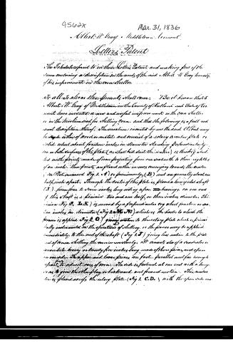
The Schedule referred to in these Letters Patent and making part of the same containing a description in the words of the said Albert W. Gray himself of his improvement in the corn sheller.
To all to whom these presents shall come: I, Albert W. Gray of Middletown in the County of Rutland and State of Vermont have invented a new and useful improvement in the corn sheller or in the machine used for shelling corn, and that the following is a full and exact description thereof. The machine invented by me the said Albert may be made either of wood or metal and consist of a rotary circular plate or wheel about fourteen inches in diameter standing perpendicular to one or both surfaces of the plate (as shall best suit the maker) is thereby divided with points made of iron projecting from one sixteenth to three eighths of an inch. These points are placed either in rows converging towards the center (as is shown in Fig. 1. & 4) or peripherally (B) and are generally about one half inch apart. Through the center of this plate is placed a horizontal shaft (T) from four to seven inches long resting upon two bearings, on one end of this shaft is a pinion two and one half or three inches diameter. This pinion (Fig. 2. & 3. & 5) is moved by a perpendicular cog wheel fourteen or sixteen inches in diameter (Fig. 2. & 3. & 5) which is the center to which the power is applied (Fig. 2. O) giving motion to the rotary plate which is peripherally constructed in the operation of shelling, or the power may be applied immediately to the end of the shaft (Fig. 1. T) giving less motion to the plate and of course shelling the corn more slowly. It consists also of a conductor or guide like twenty or thirty five inches long made of three pieces and open on one side. The upper and lower pieces are fastened parallel and far enough apart to admit ears of corn. The side is fastened at one end with a hinge so as to give the other play or backward and forward motion. This conductor is placed across the rotary plate (Fig. 1. C. D.) with the open side near
Page 3.
9562X
Mar 31, 1836
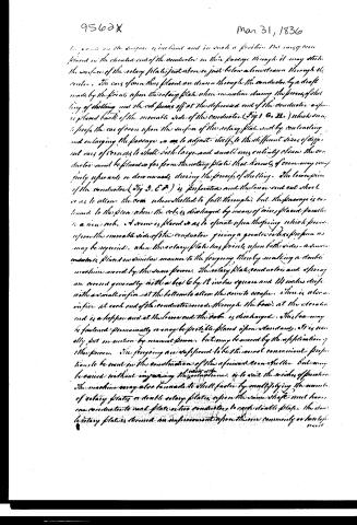
The corns on the surface is inclined and in such a position that corns can be placed in the elevated end of the conductor in their passage through it may strike the surface of the rotary plate just above or just below a line drawn through its center. The corns of corn thus placed are drawn through the conductor by a draft made by the points upon the rotary plate when in motion during the process of shelling of shelling and the corn passes off at the depressed end of the conductor as soon as it is placed back of the movable side of the conductor (Fig. 1 & 2) which serves to press the corn upon the surface of the rotary plate and by contracting and enlarging the passage so as to adjust itself to the different sizes of different corns of corns to shell both large and small corns entirely clean the conductor must be placed so far from the rotary plate that kernels of corn may completely separate or disengage during the process of shelling. The lower pin of the conductor (Fig. 3, & 4) is perforated and the lower end cut short so as to allow the corn when shelled to fall through, but the passage is continued to the floor where the corn is discharged by means of wires placed parallel to a wire rack. A screw is placed so as to operate upon the spring which presses upon the movable side of the conductor giving a greater or less pressure as may be required. When the rotary plate has pressed upon both sides a second conductor is placed in similar manner to the foregoing thereby making a double machine moved by the same power. The rotary plate, conductor and spring are covered generally with a bed 6 by 18 inches square and 14 inches deep with a small orifice at the bottom to allow the corn to escape. There is also an orifice at each end of the conductor made through the bed at the elevated end is a hopper and at the lower end the corn is discharged. This box may be fastened permanently or may be portable placed upon standards. It is usually put in motion by manual power but may be moved by the application of other power. The foregoing are supposed to be the most convenient proportions to be used in the construction of the aforesaid corn sheller but may be varied without impairing the usefulness of the machine. The machine may also be made to shell faster by multiplying the number of rotary plates or double rotary plates upon the same shaft must have one conductor to each plate or two conductors to each rotary plate. The double rotary plates is deemed an improvement upon the one commonly or barely used.
Page 4.
Mar. 31, 1836
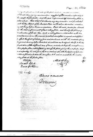
Having the fronts on both sides of the plate instead one side or surface.
I do not claim as my own invention any part of said machine separately in
her except the construction, and the said improvement of said rotary plate or
solid wheel. But what I do claim as my own invention and for which I
ask Letters Patent of the United States on the above described machine
is not being before known or used are, First the said conductor, second
ly, the said improvement of said rotary plate, and thirdly the following
combination of parts viz. such a rotary plate or solid wheel as the one
described moved in the manner in which said plate is moved and applied
to effect the object of shelling corn and combined with the conductor spring
hinge and cover as before described so constructed as to adjust itself to the dif-
ferent sizes of the different sorts of corn, and also to keep the ears of corn in
their proper place while passing across the plate giving them a proper draft
and separating the cobs from the corn combined also with the stops as before de-
scribed so placed as to cause the ears of corn to be moved and strike the circular
rotary plate at the proper place.
Witnesses
Marcell Clarke
Daniel Girdlestone
1092 words
Patented 31 March 1836
Drawing
Published accounts: journal notice
Notice in the monthly list of patents
Journal of the Franklin Institute, new ser., vol. 17 (1836), p. 439 · View the page
254. Corn sheller. Abert W. Gray, Middletown, Ver.
About this record
- Patentee
- DATAMP
- Date
- the Name and Date index of patents, DATAMP, USPTO records
- Invention
- DATAMP
- Listed in
- the Name and Date index of patents, DATAMP, USPTO records, Jim Shaw's X-patent list, the Journal of the Franklin Institute, Burke's List of Patents (1847)
- Burke's 1847 Patent Office list gives the same patent.