

Drawings and documents
National Archives restored drawings: drawing
H.W. Pitt's Patent Drawing for a Cotton Cultivator

National Archives, Restored Patent Drawings (Record Group 241) · Full-size scan at the National Archives · Catalog record
Show the text on the drawing Hide (41 words)
Words on the drawing as machine-read by the National Archives; not checked. Useful mainly for searching.
97. PLOWS / (#3) / Cotton Choppers, / $ 1- / Fintered / fl - / letter / H.W. PITTS' & / 9571-4 / PATENTEDOL Mar / DIVISTON. / Collon Cultivalor / 1836 J. / 9571X / PEF / E: / 10 / to / I' / F:
USPTO scan
The patent as scanned by the USPTO
-
 Page 1
-
 Page 2
-
 Page 3


U.S. Patent and Trademark Office · Google Patents
Show the transcription Hide (898 words)
Machine transcription (LightOnOCR) of the pages as scanned by the USPTO, most of them the handwritten copies made when the records were restored after the 1836 fire. Not checked; it can misread handwriting, so compare it with the scan.
Page 1.
9571X
H. W. PITTS.
Rotary Cultivator.
Patented Mar. 31, 1836.
M. PETERS, PHOTO-LITHOGRAPHER, WASHINGTON, D. C.
Page 2.
9571X 3-31-1836
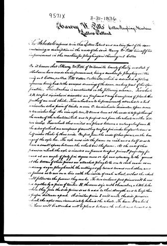
Harvey W. Pitts Cotton Ploughing Machine
Letters Patent
The Schedule referred to in these Letters Patent and making part of the same containing a description in the words of the said Harvey W. Pitts himself of his improvement in the machine for ploughing and thinning out cotton.
Be it known that Harvey W. Pitts, of Wilsonville, County of Shelby, and State of Alabama have made an improvement, being a machine for ploughing and thinning out cotton, called Pitts Cotton Cultivator, which is described as follows, reference being had to the annexed drawings of the same, making part of this specification. This machine is constructed in the following manner. Two wheels A, B, two feet six inches in diameter are prepared & may be composed of plank thus fourths of an inch thick. These wheels are to be permanently attached to a hub or circular solid piece of timber or iron C, ten inches in diameter & from seven to ten inches long. The iron axle tree, D, timber tree at the ends is to pass through the centre of the wheels (and hub) and to project out from the wheels on either side two inches. These wheels thus united are placed between a rectangular frame E, the sides of which are composed of scantling two feet five inches long and two and a half inches thick by three wide. One foot from the ends of these pieces, are the bearings of the axle tree. The axle runs into the frame one inch and a half so as to leave a small space between the wheels and the frame. At the ends of these pieces on which the axle is inserted are framed two foot pieces F, projecting forward at an angle of forty five degrees more or less, and extending to the ground. At the bottom of these pieces are attached ploughs G, one to each side, as an ordinary wagon plough with the cutting edges turned toward each other, and so formed as to run on a line with the inside of each wheel, so that the wheels will follow in the furrow they make. The two inclined foot pieces will be united together by a piece of timber H, the same size with themselves, a little below where they join the side pieces so as to add to their strength and to keep them a proper distance apart. A similar piece I will unite the side pieces in which the axles run immediately behind the wheels. The beam J to which the horse will be attached will be placed between the wheels and connected to
Page 3.
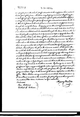
an upright piece K, which itself is attached to the cross piece that unites the hinder part of the frame. The beam may be of any convenient length, say four and a half or five feet long, and attached in front of the wheels to the cross piece uniting the inclined foot pieces by means of an iron rod and screw L. The handle M will be fastened to the side pieces and connected to a cross piece running through the end of the beam. A zigzag groove N will be formed around the hub to which the wheels are attached about an inch wide and an inch deep. Two short iron bolts O will be inserted through the beam, between the hub and the plough, and fastened to it by screws and tacks on top of the beam. These bolts will have holes in the bottom of them, in which will be inserted the end of a crank P, to be constructed after the following manner: viz, the point will sink in the holes in the bolts & it will be so placed under the beam that its end marked Q will fit into & be controlled by the zigzag groove in the hub. This will give the point R a traverse motion. To the point R a hoe with the helve inserted through the centre must be attached. It is placed horizontally & formed so as to cut both ways & of any size that may be desired. It will be attached by means of a screw and bolt & made with a space in the helve of the hoe so that it can be raised or lowered at pleasure. The hoe may walk on the ridge, or by putting an arm and brace to the beam, or curving it the horse may be made to walk on one side. By having one or more hoes of different sizes, any quantity of the cotton required may be cut out. This machine may likewise be used for other purposes. For a further illustration of my invention I refer to the model of the same deposited in the Patent Office. What I claim as my invention and which I desire to secure by Letters Patent consists in the machine for ploughing and thinning out cotton, called "Pills Cotton Cultivator" as before described.
Witnesses
Sam Stullins
Gilbert L. Gibson
Henry W. Pills
About this record
- Patentee
- DATAMP
- Date
- the Name and Date index of patents, DATAMP, USPTO records
- Invention
- DATAMP
- Listed in
- the Name and Date index of patents, DATAMP, USPTO records, Jim Shaw's X-patent list, Burke's List of Patents (1847)
- Burke's 1847 Patent Office list gives the same patent.