

Drawings and documents
National Archives restored drawings: drawing
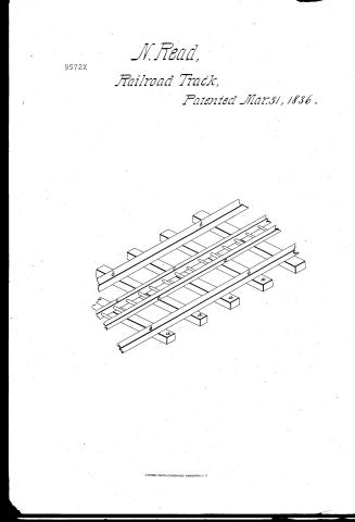
Nathan Reid's Patent Drawing for an Improved Rail Road

National Archives, Restored Patent Drawings (Record Group 241) · Full-size scan at the National Archives · Catalog record
Show the text on the drawing Hide (35 words)
Words on the drawing as machine-read by the National Archives; not checked. Useful mainly for searching.
104. RAILWAYS, / Rails; Rack. / 0 118 IID is / classigication / IMPROVED / 95424 / R a i I / DIVISION. / 9572X / Paienied March 617 1836. / Reston Pats. vol. 27.p. 69.
USPTO scan
The patent as scanned by the USPTO
-
 Page 1
-
 Page 2
-
 Page 3


U.S. Patent and Trademark Office · Google Patents
Show the transcription Hide (833 words)
Machine transcription (LightOnOCR) of the pages as scanned by the USPTO, most of them the handwritten copies made when the records were restored after the 1836 fire. Not checked; it can misread handwriting, so compare it with the scan.
Page 1.
N. Read,
Railroad Track,
Patented Mar. 31, 1836.
Page 2.
9572X
Mar. 31, 1836
Nathan Read. Belfast. Maine
Letting Patent
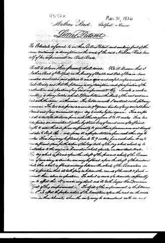
The Schedule referred to in this Letter Patent and making part of the same containing a description in the words of the said Nathan Read himself of his improvement in Rail Roads.
To all to whom these presents shall come. We it known that I Nathan Read of Belfast in the County of Waldo and State of Maine have invented constructed and applied to use a new and useful improvement in Rail Roads and that the following is my description and specification of the construction and operation of my said improvement viz. I make a machine resembling a strong ladder which I place between the Rails of the road and on a level with the same or thereina. This ladder or rack I construct in the following manner. The two side pieces are made of square timber of any suitable kind of wood and of any convenient size, say 6 inches by ten or more. These are placed at a suitable distance from each other say from 5 to 10 inches. These two side pieces are connected together by stout bars of iron or iron of sufficient length to enter the side pieces sufficiently to give them a permanent and strength and also to keep the side pieces at a proper distance from each other say 6 inches. These bars may be placed from 6 to 9 inches from each other so as to give sufficient space for the action of the long teeth of the cog wheel which is to be attached to the engine or locomotion which operates on said Rail Road. This cog wheel is placed upon the shaft of the powered wheel of the Locomotive or every a similar one may be placed upon the shaft of the windmill wheel this wheel is placed midway between the wheels of the Locomotive in such a position that its teeth press in between the rounds of the rack & push against them when in operation. The wheel is made of a diameter sufficiently large to effect this. It is made very stout and its teeth larger than common.
Object of this improvement. The object of this improvement is the following viz. 1st To effect the proper action of the locomotive upon the road in the winter season in those climates where the rails may be encumbered with ice and
Page 3.
9572x
Mar 31, 1836
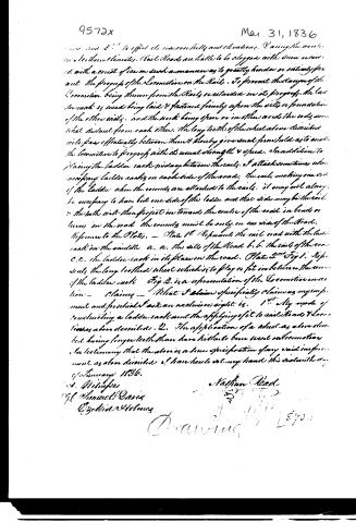
now and 2" to effect its necessary elevations. During the winter in Northern climates, Rail Roads are liable to be clogged with snow covered with a coat of ice in such a manner as to greatly hinder or entirely prevent the progress of the Locomotive on the Rails. To prevent this danger of the Locomotive being thrown from the Rails or retarded in its progress, the ladder rack is used being laid & fastened firmly upon the rails or foundation of the other rails, and the work being open or in other words the rods somewhat distant from each other, the long teeth of the wheel above described will pass effectually between them & thereby give such firm hold as to enable the locomotive to progress with its usual strength & speed. In addition to fixing the ladder rack midway between the rails, I attach sometimes when necessary ladder racks on each side of the road, the rails making one end of the ladder when the rounds are attached to the rails, it may not always be necessary to have but one side of the ladder and that side may be the rail & the teeth will then project in towards the centre of the road in bends or turns in the road the rounds must be only on one side of the Road.
Reference to the Plates. — Plate 1st Represents the rail road with the ladder rack in the middle a. a. the rails of the Road b. b. the ends of the road c. c. the ladder rack in its place on the road. Plate 2nd Fig 1. Represents the long toothed wheel which is to play or fit in between the rounds of the ladder rack Fig 2. is a representation of the Locomotive in action.
Claiming — What I claim specifically claiming as my improvement and for which I ask an exclusive right is. 1st My mode of constructing a ladder rack and the applying of it to rail Roads & Locomotives above described. 2. The application of a wheel as above described having longer teeth than have hitherto been used on locomotives, so testimony that the above is a true specification of my said improvement as above described I have here to set my hand this 31st day of January 1836.
Nathaniel Read
J. W. M.
Wm. Samuel Davis
Exhibit 2460003
Drawing 1870
Published accounts: journal notice
Notice in the monthly list of patents
Journal of the Franklin Institute, new ser., vol. 17 (1836), p. 439 · View the page
271. Rail roads.-Nathan Reed, Belfast, Maine,
Published accounts: journal notice
Notice in the monthly list of patents, with remarks
Journal of the Franklin Institute, new ser., vol. 18 (1836), p. 316 · View the page
13. For a Saw mill dog, or carriage stock; Jesse Reed, Marshfield, Plymouth county, Massachusetts, March 2.
Remarks. Various modes of forming dogs for holding, and slides for setting, the logs on saw mill carriages, have been made the subject of patents. The things claimed by the present patentee, are a "notched slider, a hand, weight and lever, a lock joint of a knee, a swivel brace, right angled dogs, and the method of confining them, as described, with their arrangement." Some of the parts individually claimed are not new; as, for example, the notched slider, which is a bar of iron forming a rack on its lower edge, and having the right angled dogs on its upper side. The notches, or teeth, on the lower side of the slider, are for setting the log, which is to be effected by the running back of the carriage, in a manner very similar to that adopted by Phineas Bennett. The mode of action is not exhibited sufficiently in detail, to instruct a workman, we cannot, therefore, speak with confidence respecting its originality.
About this record
- Patentee
- DATAMP
- Date
- the Name and Date index of patents, DATAMP, USPTO records
- Invention
- DATAMP
- Listed in
- the Name and Date index of patents, DATAMP, USPTO records, Jim Shaw's X-patent list, the Journal of the Franklin Institute, Burke's List of Patents (1847)
- The Franklin Institute's journal gives a different date.
- Burke's 1847 Patent Office list gives the same patent.