

Drawings and documents
National Archives restored drawings: drawing
Daniel Garish's Patent Drawing for a Saw Mill

National Archives, Restored Patent Drawings (Record Group 241) · Full-size scan at the National Archives · Catalog record
Show the text on the drawing Hide (31 words)
Words on the drawing as machine-read by the National Archives; not checked. Useful mainly for searching.
U'S / 0 A / of / bi / 10 / of / 60 o o / res / at / 574 / by / ty / It / NE / III
USPTO scan
The patent as scanned by the USPTO
-
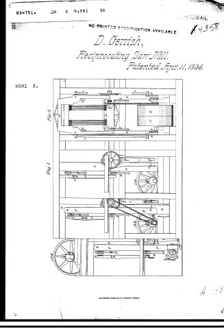 Page 1
-
 Page 2
-
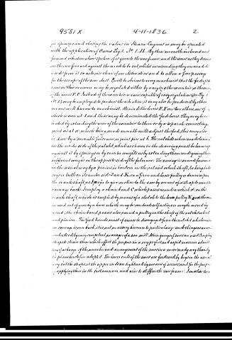 Page 3
-
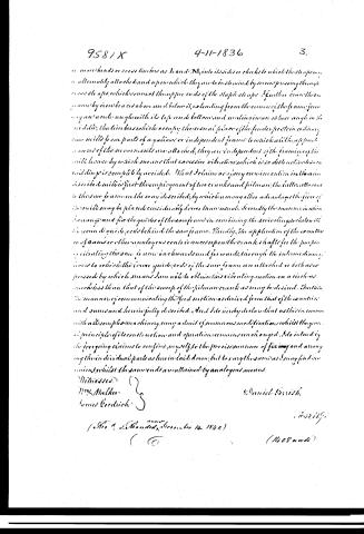 Page 4


U.S. Patent and Trademark Office · Google Patents
Show the transcription Hide (1,451 words)
Machine transcription (LightOnOCR) of the pages as scanned by the USPTO, most of them the handwritten copies made when the records were restored after the 1836 fire. Not checked; it can misread handwriting, so compare it with the scan.
Page 1.
83-751. OR X 9,581 SR
NO PRINTED SPECIFICATION AVAILABLE
D. Gerrish,
Reciprocating Saw-Mill.
Patented Apr. 11, 1836.
9581 X.
Fig 2
Fig 1
A.M. PHOTO-LITHO. CO. N.Y. (OSBORNE'S PROCESS)
Page 2.
9581X 4-11-1836 1.
Daniel Gerrish.
Letters Patent. Valued April 11th 1836.
The Schedule referred to in this Letters Patent and making part of the same, containing a description in the words of the said Daniel Gerrish himself of his improvement in the Saw Mills.
To All Men to Whom It May Concern: Be it known that I David Gerrish of Portsmouth in the State of New Hampshire have invented certain improvements in the construction of saw mills and I do hereby declare that the following is a full and exact description thereof, reference being had to the drawings which accompany and make a part of this specification. Fig. 1. in the accompanying drawings is an elevation of the saw yoke and its appurtenances, as seen in a diagram of the mill, a portion of the frame work being removed to exhibit the construction of the essential parts in a more distinct manner. Fig. 2. is an elevation of the saw yoke and other parts in both figures when the same parts are shown they are indicated by the same letters. A. A. is the saw frame which is moved up and down by means of the crank B. B. there being as seen in the drawing, a crank on each end of the crank shaft and two pitman C. C. leading from them, one to each side of the saw frame, to which I attach them by a joint pin, at a considerable height, say at, or above the middle of the frame by which means the pitman may have sufficient length to operate advantageously with a much less elevation of the floor of the mill than is usually required. The saw frame does not slide in fixed posts, but is guided with vibrations by the sockets D. D. which are fitted to, and slide upon the round rods E. E. The sockets D. D. are made to vibrate upon guides or joint pins in the manner shown in the drawings, instead of being immovably attached to the saw frame, as this frame besides its vibratory motion up and down, has one also back and forward, which is given to it in a way and for the purpose to be now described. The upper and lower guides F. F. 1. 1. 2. 2. E. E. B. B. also the inner guides G. G. F. F. Fig. 1 and 2 instead of being attached to the fixed posts or to any part of the frame work of the mill is affixed to the vibrating levers F. F. hung by pins at their upper ends to the posts E. E. as seen in the several figures. The vibrating levers receive their motion from the eccentric H. H. operating like the crank.
Page 3.
for opening and closing the valves in Steam Engines or may be operated with the application of Pans Fig. 1. No. 1. II. By these means the backward and forward vibration above spoken of is given to the saw frame, and the saws as they descend are thrown forward against the wood to be cut, whilst in ascending they are made to recede from it so as to give clear space between them and to allow a free passage for the escape of the saw dust. It will be obvious to every machinist that the feed of the saw in this manner may be regulated either by varying the eccentric, or the saws of the lever E. E. Instead of the eccentric a cam, capable of easy regulation (see Fig. 1. No. 1.) may be employed to produce the vibration; it may also be produced by other means well known to machinists. Being in the levers E. E. are two others, one of which is seen at I and the other may be denominated the feed levers. They may be isolated by extending the arms of the eccentrics to them or by a separate connecting point as at a, which being made movable will adjust the feed; this may also be done by a movable fulcrum, or joint pin at b. The pallets when made down in the under side of the pallet wheel as shown in the drawing must be borne up against it by springs or by counter weights as by extending them and giving them sufficient weight on the opposite side of the fulcrum. The carriage is moved forward in the usual way by a pinion, or lantern on the pallet wheel shaft, taking into cogs or teeth on its under side I and K on a firm and loose pulley or drum upon the crank shaft, as I prefer to give motion to the saw by means of a shaft to transmit carriage back. I employ a chain band C which passes round a wheel D on the crank shaft, which is coupled by means of a clutch to the loose pulley K and thrown in and out of gear by a lever which may be rendered self acting or may be moved by hand; the chain band passes also round a pulley on the shaft of the pallet wheel and pinion. The feed bands must of course be disengaged from the pallet wheel when the carriage is run back, it is not necessary however to particularize such things as are understood by every competent manager of a saw mill. When gangs of saws are used I employ straps to strain them which effect the purpose in a very perfect and rapid manner admitting of a change of the number and arrangement of the saws in a very ready way than by the plans heretofore adopted. The lower ends of the saws are fastened by keys in the usual way but the straps at the upper end are tightened by means of screws, and for the purpose of applying these in the best manner, and also to stiffen the saw frame. I omit the lever
Page 4.
958 / X 4-11-1836 3.
or in the heads or cross timbers as I and M, into its sides or cheeks to which the staples or alternately attached and upon which they are to be steamed by screws pressing through cross staples, which connect the upper ends of the staple staples. I further brace them by iron braces above and below it, extending from the corners of the frame, forming an acute angle with its top and bottom and meeting in an acute angle in the middle, the timbers which occupy the usual place of the fender posts in ordinary saw mills from parts of a gallooner or independent frame to which all the apparatus of the movements are attached, they are independent of the framing of the mill house by which means that excessive vibration which is so destructive to a building is completely avoided. That I claim as my own invention in the manner described is first the employment of two cranks and pitman, the latter attached to the saw frame in the way described, by which among other advantages the drive of the mills may be placed considerably lower than usual. Secondly the manner in which I arrange and fix the guides of the saw frame in combining the revolving wheels with the seen & guide posts behind the saw frame. Thirdly, the application of the eccentric or of cams or other analogous tools in excess upon the crank shafts for the purpose of yielding the saw frame backward and forwards, through the intermediate arcs to which the lower guide posts of the saw frame are attached or both as expressed by which means I am able to obtain this vibrating motion on a circular much less than that of the sweep of the pitman crank as may be desired. Fourthly, the manner of communicating the feed motion as derived from that of the eccentric and cams and herein fully described. And I do hereby declare that as this invention with all its complex machinery may admit of numerous modifications whilst they preserve principles of its construction and operation remains unchanged. I do intend by the foregoing claims to confine myself to the precise manner of fixing and arranging the individual parts as herein laid down, but to vary the same as I may find convenient, whilst the same ends are attained by analogous means.
Witnesses:
Wm. Walker
James Goodrich
Daniel Griswold
Filed & Recorded December 14, 1840.
(1408 words)
Published accounts: journal notice
Notice in the monthly list of patents
Journal of the Franklin Institute, new ser., vol. 18 (1836), p. 71 · View the page
279. Saw mill.-Daniel Gerrish, Boston, Mass.
DATAMP: illustration
Illustrations from DATAMP
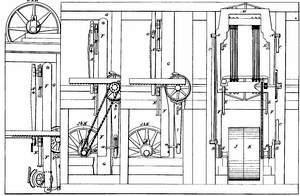

DATAMP (Directory of American Tool and Machinery Patents), via the Internet Archive · Archived DATAMP page
About this record
- Patentee
- DATAMP
- Date
- the Name and Date index of patents, DATAMP, USPTO records
- Invention
- DATAMP
- Listed in
- the Name and Date index of patents, DATAMP, USPTO records, Jim Shaw's X-patent list, the Journal of the Franklin Institute, Burke's List of Patents (1847)
- Burke's 1847 Patent Office list gives the same patent.