

Drawings and documents
National Archives restored drawings: drawing
Samuel G. Merriman's Patent Drawing for Cutting Teeth of Circular and Other Saws

National Archives, Restored Patent Drawings (Record Group 241) · Full-size scan at the National Archives · Catalog record
Show the text on the drawing Hide (45 words)
Words on the drawing as machine-read by the National Archives; not checked. Useful mainly for searching.
METAL WORKING, / NG. / saws sharpening, / Rotating Tool. / vital Biv. 14. W oking This / 50-749 / Saw Sharpiering / CLASSIFICATION / 95824 / DIVISION: / 9582 / butting Juth of circular & other Sans. / Fat: "April 1836. / ti / Ge
USPTO scan
The patent as scanned by the USPTO
-
 Page 1
-
 Page 2
-
 Page 3
-
 Page 4
-
 Page 5


U.S. Patent and Trademark Office · Google Patents
Show the transcription Hide (1,270 words)
Machine transcription (LightOnOCR) of the pages as scanned by the USPTO, most of them the handwritten copies made when the records were restored after the 1836 fire. Not checked; it can misread handwriting, so compare it with the scan.
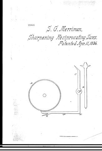
Page 1.
9582X
S. G. Merriman,
Sharpening Reciprocating Saws.
Patented Apr. 11, 1836.

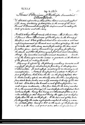
Page 2.
9582X
April 11, 1836
1. 250
Samuel O. Merriam of Southington, Connecticut.
Letters Patent.
The Schedule referred to in these Letters Patent and making part of the same, containing a description in the words of the said Samuel O. Merriam himself of his improvement in cutting the teeth of circular and other saws.
To all to whom these presents shall come: Be it known that I Samuel O. Merriam of Southington in the County of Hartford and State of Connecticut have invented a new and useful improvement in the mode and method of cutting the teeth of circular and other saws, and also for cutting the saws used for cotton gins, and in the machinery necessary for effecting the same, and that the following is a full and exact description thereof. My invention and improvement consists in . . . combining the motion of a circular index or graduated with the stroke of the punch in cutting the teeth.
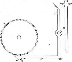
This may be effected by the following machinery connected with any press properly constructed for punching or stamping iron or other metals. To such a press, considering it as standing in its usual position. I attach two projections or studs to the front part of the frame, both below the die in the press & from six to twelve inches apart, one directly above the other, and projecting from six to twelve inches more or less according to the size of the saw to be cut. In a hollow box be made in each of these projections, one inch or more in diameter. Into these boxes let the axles (marked A in the annexed drawings) be inserted perpendicularly about twelve inches in length, having two bearings or shoulders so fitted as to revolve steadily in said boxes and having the upper end as high or higher than the die in the press. To the lower end of this axle fix horizontally the index or graduated marked B which is a circular metallic plate having a hole in the centre of the proper size to fit on to the lower end of said axles, when it is firmly secured
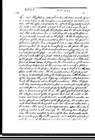
Page 3.
9582X 4-11-1836 2.
254.
by a nut. This plate or index should have the same number of notes, or indentations on the circumference as intended to cut into the saw. At the upper end of said axle attach horizontally and fasten with a nut the plate intended to be cut into a saw, having a hole punched in the center for that purpose and let the axle be so fixed that when it revolves it will bring the edge of the plate on to and directly over the line in the profs. In the back part of the frame of the profs is inserted a pivot and on this pivot is placed an upright lever (marked C) in or near the center at the point marked D, so as to move freely on the pivot, the upper end of the lever being bent inward and over a projection on the movable part of the profs. On the lower end of the lever at the point (marked E) by a joint, attach a horizontal rod (marked F) of the proper length and direction, having the end a little thicker or knurled so as to play into the indentations of the circular index being supported at the end near the index by a plate or loop fastened to the profs, or its frame so as to keep it in the same plane with the index. The die and punch in the profs must of course be suitable for cutting the teeth required. At the lower end of the lever near the joint, a spring or weight is attached to draw back the horizontal rod as hereafter mentioned. When the profs with this machinery attached is put in motion for use, the spring movable part as it rises will profs by its projection against the upper or inner end of the lever, the effect of which will be to prof the sharpened end of the horizontal rod into the notch in the index and cause it with the axle and the plate to rotate, and as the upright movable part of the profs falls, the weight or spring will draw back the horizontal rod into the next indentation of the index. This rod is constantly pressed upon the index by a spring marked in the drawings G. Thus every time the profs rises, the index and plate by means of the lever will rotate so far as is necessary for the teeth required, and each fall of the profs will by means of the punch and die cut out a piece from the
Page 4.
9582X 4-11-1836 3.
the plate so as to form a tooth, and at the same time the spring weight will draw back the horizontal rod to the next indentation. The index may be formed by placing pins at a proper distance near the circumference of the index and at right angles with it, and in many other ways, in which case the lines should be made to correspond with the index and the operation will be the same. If it is required to cut a saw with a straight edge, the same index may be used, and the plate to be set placed upon the disc of the press and be made to move in a right line by means of a rack and pinion attached to the axis. When it shall be required to cut a saw plate with half the number of teeth on the index, this may be effected by raising the rising frame of the press, with its projection to rise so high as to force the horizontal rod to push the index two notches instead of one at each rise and fall. Different dies and punches may be used if necessary. For a more full illustration reference may be had to the drawings annexed as part of this specification, and to the model deposited in the patent office.
From the operation of this machinery saw teeth are cut with great expedition and great accuracy, and as a result from this invention it is no longer necessary that a saw plate should be made exactly circular before the teeth are cut. Nor if a square or any irregular plate is brought under the operation of this improved machine it will of necessity produce a saw perfectly circular of course much trouble and expense is saved in preparing the plates. I do not claim as my invention the press or other machinery heretofore used for cutting the teeth of saws by punch and die, nor do I claim as my invention an index or graduated as such, singly, and alone, both have been long known and used separately. But I do claim as my invention the combination or combined use of the index or graduated with the punch and die connected with any machinery or press for cutting saw teeth or all or any
Page 5.
9582X 4-11-1836
Description in the manner and on the principles, as specified above, and for that combination and the machinery now say to effect the same as above specified & solid letters Patent. Dated this 19th day of March 1836.
Witneses
Homer Lowrey
Roger Hillery
Samuel G. Merriam
(13130001)
Drawing
Published accounts: journal notice
Notice in the monthly list of patents
Journal of the Franklin Institute, new ser., vol. 18 (1836), p. 71 · View the page
274. Cutting saw teeth.-Samuel G. Merriman, Southington, Conn.
DATAMP: illustration
Illustrations from DATAMP

DATAMP (Directory of American Tool and Machinery Patents), via the Internet Archive · Archived DATAMP page
About this record
- Patentee
- DATAMP
- Date
- the Name and Date index of patents, DATAMP, USPTO records
- Invention
- DATAMP
- Listed in
- the Name and Date index of patents, DATAMP, USPTO records, Jim Shaw's X-patent list, the Journal of the Franklin Institute, Burke's List of Patents (1847)
- Burke's 1847 Patent Office list gives the same patent.