

Drawings and documents
National Archives restored drawings: drawing
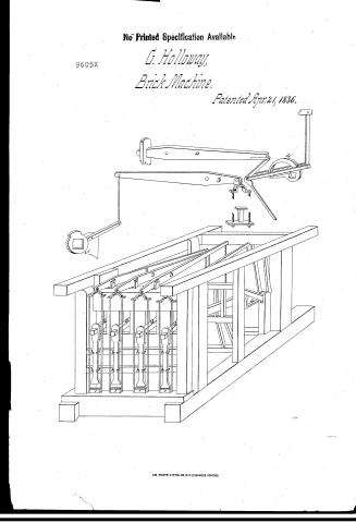
Gooding Holloway's Patent Drawing for a Brick Machine

National Archives, Restored Patent Drawings (Record Group 241) · Full-size scan at the National Archives · Catalog record
Show the text on the drawing Hide (66 words)
Words on the drawing as machine-read by the National Archives; not checked. Useful mainly for searching.
Clay & Pour / Brink Machines, / Peoss Box Mold; Stationary, / Compacting Single Surface, / DIV. 15 / f2. / GOODING HOLLOWAY / 9.605. x / BRICK MACHINE / DIVISION. / vot. 27.7377 / 9605X / Patented April 21. 1836. / References / 1 working moulds / main leavers. / 4 lam / 3 Discharging leavers. / OR / Patenl offer Decl1888 / Made under the direction of the Commitainer / of Patents in comformity with act 3. Marching
USPTO scan
The patent as scanned by the USPTO
-
 Page 1
-
 Page 2
-
 Page 3
-
 Page 4
-
 Page 5
-
 Page 6


U.S. Patent and Trademark Office · Google Patents
Show the transcription Hide (1,994 words)
Machine transcription (LightOnOCR) of the pages as scanned by the USPTO, most of them the handwritten copies made when the records were restored after the 1836 fire. Not checked; it can misread handwriting, so compare it with the scan.
Page 1.
No Printed Specification Available
9605X
G. Holloway,
Brick Machine.
Patented Apr. 21, 1836.
AM. PHOTO-LITHO. CO. N.Y. (OSSORNE'S PROCESS)
Page 2.
4/21/1836 9605X
April 21, 1836 377.
Gording Holloway of Miamisburg Ohio
Letters Patent
The Subscribers refer to in their Letter Patent and making part of the same enclosing a description in the words of the said Gording Holloway himself of his improvement in the machine for making and pressing Bricks from moist or untempered clay.
To all to whom these presents shall come. Be it known that I, Gording Holloway of the Town of Miamisburg in the County of Montgomery and State of Ohio have invented a new and useful machine, including the frame and ground work supporting the same for making and pressing Bricks, from moist or untempered clay, and that the following is a full and exact description thereof as placed upon its foundation and frame for working four moulds abreast (but may vary in dimensions according to the number of moulds to be used).
The ground or main dills to be 18 by 21 in sq. The longest or side ones 22 ft. and the end or short ones 14 ft. in length, with a suitable number of ties, or girders, to hold them firmly in place. The string pieces 7 ft. 9 in long to be framed into the middle or centre ties and the cast or back dills 8 inches sq. for the purpose of receiving the feet of the long beams. The main side dills meet where the frame is a plate may be 32 feet long in order to cover a frame to cover the main or driving wheel 10 ft. of it reducible to 8 in sq.
On each end of the front side dills stands a post 6 by 8 in sq. extending into the plate above into which are framed two or 3 pieces, two feet apart and the lower one 18 in above the dills for holding the clamps to confine the motion or constraining bars in their places of perpendicular action as hung upon the ends of the long beams. Immediately behind or 4 in from the front dills are placed two main posts 18 in sq. & 10 1/2 feet high from the top of the dills to the under side of the plate (which plate should be 8 in sq. and corresponding length of the dills) mortised through the main dills and let in with dove tail tenons well pinned and also secured by strong iron straps passing under the dills and bolted.
Page 3.
4/21/1836 9605x
3/8.
through the first 12 in above the lower. Into these posts are framed two main beams. The upper one 18 by 2 1/2 in sq. and the lower one 18 by 12 in with double tenons. They are to be placed 21 in apart and the lower one 5 ft. above the main deck, let in as the a radius of 3 in to the posts and between them are to be placed 8 pieces or uprights 7 in wide and 3 in thick framed in by braces for the purposes of hanging and confining the main or long lances. On the top of the upper beam are placed 44 short posts, on which hang the discharging lances 3 feet 3 in in rear of the forward main posts are placed two more posts 8 in square, of same height as the others, which receive or contain two more lances with uprights, same in number as the forward ones but 1 1/2 in larger, 2 by 4 in sq. and 2 ft 7 in long, to serve as guides for the lances ends of the main braces. 5 ft. 3 in behind the last named or middle posts on the right hand side, is to stand another 12 in sq. of equal height to receive the end of the shaft on which the lances are fixed, and on the opposite side next the main wheel are placed two other posts in the deck 3 1/2 ft. apart of like dimensions, into which are let or slipped two 20 ft. pieces 3 ft. long and of suitable size to receive the ends of the beam wheel and other wheel shafts. The former to be 14 1/2 ft. from the top of the deck to the centre of the shaft. Immediately in front of the same main post that contains the beam wheel which is placed a piece of timber 8 in sq., into this are let 4 posts 6 ft high, in the top of which hang the short lance lances, by means of connecting rods. Into the upper end of the beam wheel main post and the opposite plate is inserted a beam or cross piece, to which are attached the perpendicular and corresponding bars of the double lance rods, connected with the joint lances. That part of the frame containing the main driving wheel is connected with the first already described and should be of corresponding dimensions. The main or great wheel to be 14 ft. in dia. and placed near the top of its vertical shaft of 24 inches diameter, to be moved or propelled by an iron or steam power. The former by inclined planes or at the end of a horizontal bar 14 ft. from the shaft and 2 ft. from its base. Into the main cog wheel plays a spur wheel 21 inches di
Page 4.
4/21/1836 9605x
377
another placed on the end of a shaft 8 ft. long. At the other end is another spur wheel of some size playing into a wheel 8 ft. diameter which turns a shaft whereon is placed Rams that move the joint and main long levers, as well as the Rams for working the discharging levers. The aforesaid Rams may be made of wood strengthened with iron, or wholly of cast iron 2½ ft. in length from the centre of the shaft on which they are placed to the front or end of the ram in shape of bellows D. The small Rams to operate the discharging levers should be 1½ in. in length and fit the distance round the shaft for the purpose of raising and holding up the block sufficient time for removal.
The first mentioned Rams, which move the joints and long levers, act between two iron rods attached to the joint at the joint levers by means of a bolt passing through the whole of them. So the other end of these rods is placed a friction roller against which the Rams strike in moving round. These rods are attached to the end of the long levers, and hung at the upper end by a bolt or hook. The lower part of the joint lever is 5 ft. long and the upper part 2 ft. 9 in. each measuring from the centre of the joint. The upper end is connected by means of a joint to the end of the long lever working under it. The lower end of the joint lever is hung by and plays on a bolt passing through it and the strong piece in which the foot rests.
The main lever is 12 ft. long and 1½ in. thick and 16 in. at the widest part when it is hung by a 2 in. iron bolt playing in iron box within 2½ ft. of the forward end and tapering to 1½ in. at the other. The ascending or pressing force is applied by means of a friction bar or piece of timber of suitable size to enter the mould at the lower end, which is to be faced with iron or steel polished entirely smooth. The upper part of the bar to be sufficiently wide to hang upon the end of the of the main lever by means made sounding on the under side and is confined to its perpendicular position by the means before mentioned. The blocks when pressed are raised out of the mould by means of the discharging levers (working above the main levers) which are moved by the small Rams acting upon the sheet
Page 5.
380.
beams, connected by a rod with the said delivering lines 11 1/2 feet in length and being 2 1/2 ft. from the fore end where it is 6 in. wide and 2 in. thick; tapering to a square, same as the long beams. On the front end is hung a slings or bail at each end of which small rods, 15 in. apart are attached reaching down through the main front sill on each side of the mould and through each end of a cross bar of iron or timber, on the centre of which stands a short post or stem for the purpose of lifting up the bricks to the top of the mould, fastened by nuts or screws on the end of the rods. The short beam connected by a rod with the delivering lines is 11 ft. 3 in. long & 2 by 2 in. square and is hung 12 in. from the end of the same.
The lower part of the same beams are connected by rods, 5 ft. 8 in. long. The moulds which are to be laid into the main front sill may be set whole or in 4 pieces and put together by screws, the latter joint is preferable, on account of polishing the inside more perfectly smooth which is essentially necessary. The top may be half an inch thinner for the purpose of pressing the bricks more solid at the ends. The lower or bottom part to be a plate of iron or steel fitted and fastened upon a block of wood to fit the mould as close as possibly consistent with its movement, to the centre of which also is attached the stem passing down through the sill and fastened to the bottom of the aforesaid moving slings for raising the bricks out of the moulds as previously described. A screen for the purpose of pulverizing, sifting and cleaning the clay is made of iron 11 ft. 2 1/2 feet diameter and 6 ft. long fastened upon a rod with bands of steel iron on each end of 4 inches wide, and a second one 12 in. ground of the first, one foot in width for the purpose of protecting that part of the screen where the clay is thrown in. The wheel to be driven by a band or rope passing round a wheel upon the stone wheel shaft 4 1/2 in. round a wheel fastened upon the shaft of the rod placed so near the moulds that one end or great gear may be let into one of the main front posts and the other into a smaller one erected for the purpose of supporting the same. What I claim as my own in
Page 6.
4/21/1836 9605x
381
vention and not previously known in the above described machine, and its grand work is, in the first place, the general construction of the frame supporting and containing the whole machinery. Secondly I claim the application of the joint lever to the end of the long or main lever, whereby superior power is obtained. Also the bars, or double camrods, through which the cam passes. Also the friction rollers as fixed in the end of the same against which the cam strikes when moving round. Also the suspending bars and the way and manner they are attached to the frame rods. Also the application of the long and short discharging levers with the manner of hanging and connecting the arms. The slip, also, is hung by a screw upon the end of the discharging lever for the purpose of raising the brick out of the moulds as also the small levers before described. I further claim the improved construction, position, and projecting of the bars, and in conclusion, the combined application and application of the three different power principles embraced in and by the bars, joint lever and main long lever, any two of them to be used or worked by steam, animal or hand power in any machine for one or more moulds, for the several purposes of making and pressing bricks from moist or untempered clay.
Witnesses
Thomas Johns
Chas. M. Keller
Goding Walloway
(2114 words)
(Patented April 21, 1836)
Drawing
Published accounts: journal notice
Notice in the monthly list of patents
Journal of the Franklin Institute, new ser., vol. 18 (1836), p. 71 · View the page
299. Brick machine.-Gooding Halloway, Montgomery county, Penn.
About this record
- Patentee
- DATAMP
- Date
- the Name and Date index of patents, DATAMP, USPTO records
- Invention
- DATAMP
- Listed in
- the Name and Date index of patents, DATAMP, USPTO records, Jim Shaw's X-patent list, the Journal of the Franklin Institute, Burke's List of Patents (1847)
- Burke's 1847 Patent Office list gives the same patent.