

Drawings and documents
National Archives restored drawings: drawing
Joseph Turner's Patent Drawing for Double Lever Power

National Archives, Restored Patent Drawings (Record Group 241) · Full-size scan at the National Archives · Catalog record
Show the text on the drawing Hide (46 words)
Words on the drawing as machine-read by the National Archives; not checked. Useful mainly for searching.
185. MECHANICAL MOTORS. / Miscellaneous. / ts / pt / Jusepto Turners Patented 6th / May 1836. / DOUBLE LEVER POWER / 9642-X / DIV ISION. / Claim the purchase delained / to perfect engantees / by the double lever and its affication
USPTO scan
The patent as scanned by the USPTO
-
 Page 1
-
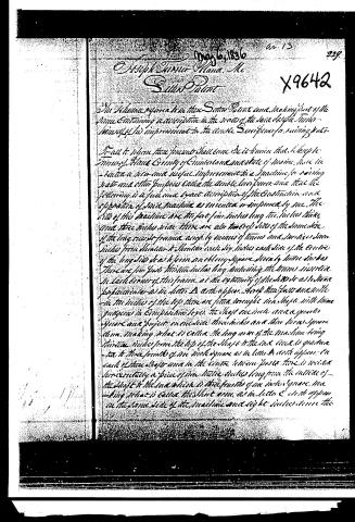 Page 2
-
 Page 3


U.S. Patent and Trademark Office · Google Patents
Show the transcription Hide (784 words)
Machine transcription (LightOnOCR) of the pages as scanned by the USPTO, most of them the handwritten copies made when the records were restored after the 1836 fire. Not checked; it can misread handwriting, so compare it with the scan.
Page 1.
9642X
J. Turner,
Mechanical Movement.
Patented May 6, 1836.

A.M. PHOTO-LITHO. CO. N.Y. (OSBORNE'S PROCESS)
Page 2.
May 6, 1836
Joseph Turner, Plana, Me
Said Patent
The Scheme refers to the said Patent and making part of the same containing a description in the words of the said Joseph Turner himself of his improvement in the double Screw for raising water.
It will be seen that present shall come to it known that Joseph Turner of Plana County of Cumberland and state of Maine, have invented a new and useful improvement in a machine for raising water and other purposes called the double Screw and that the following is a full and exact description of the Construction and operation of said machine as invented or improved by me. The sides of this machine are thirteen feet long, two inches thick and three inches wide. There are also two cross sides of the same size of the long sides of frame, as by means of timbers and braces, three inches from shoulder to shoulder, each side inches each side of the centre of the long sides so as to form an oblong square, nearly twelve inches. There are four posts thirteen inches long, including the timbers inserted in each corner of this frame, at the extremity of the sides so as to stand perpendicular as in letter A as it appears. At the four posts and in the middle of the top there are fitted wrought iron shafts, with three gradings in circumference, seven feet one inch and a quarter square and project on one side three inches and three inches square down, making what is called the long arm of the machine being thirteen inches from the top of the shaft to the end and is graduated to three fourths of an inch square as in letter B as it appears. On each of these shafts and in the centre between posts there is inserted horizontally a piece of iron twelve inches long from the outside of the shaft to the end which is three fourths of an inch square, making what is called the short arm, as in letter C as it appears on the same side of the machine and eight inches down the
Page 3.
290 X9642
Let there be fitted a bar lengthwise of the machine and secured at each end of the frame so as to be immovable, and to the ends of this bar there be a motion made right inside long and one and a half inches wide through which a two-thick foot long arm one inch and a half square and is fastened by an iron pin through the center of the motion and a six inches from the long end of the bar as in letter (D) doth appear. And the top of this bar is fitted a rod from part to six feet long and one inch in diameter by which the lever is fitted and the lever is put proper should have the long arms pointing directly down, making the distance back way from the end of the lever to the end of the long arm twelve inches then there is a motion made in the end of the bar and in the end of each of the long arms so as to permit the iron rods one inch wide and three eighths of an inch thick to put together in the lever as to form a joint in one iron pin. The other rods are fitted one each way in the end of the long arms with iron pins as in letter (E) doth appear. This is used to raise water then fitted on the top of a pump rod or piston made fast to the end of the short arms and is put in motion by taking hold of the rod which is made fast in the top of the lever and thus giving the arm the motion generally used in working. This frame may be fitted on the pumps box or some set at any distance as much by lengthening or shortening the frame as the case may require and turning the short arms to the side.
That I claim as my invention and not joining know in the above described machine is the purchase obtained by the double lever and its application to pump engines &c &c.
Witnesses
John H. Hunt
Joseph H. Foster
Joseph Hunt
1741.10.7
D. C. H.
Published accounts: journal notice
Notice in the monthly list of patents
Journal of the Franklin Institute, new ser., vol. 18 (1836), p. 143 · View the page
341. Raising water. Joseph Turner, Poland, Maine,
About this record
- Patentee
- DATAMP
- Date
- the Name and Date index of patents, DATAMP, USPTO records
- Invention
- DATAMP
- Listed in
- the Name and Date index of patents, DATAMP, USPTO records, Jim Shaw's X-patent list, the Journal of the Franklin Institute, Burke's List of Patents (1847)
- Burke's 1847 Patent Office list gives the same patent.