

Drawings and documents
USPTO scan
The patent as scanned by the USPTO
-
 Page 1
-
 Page 2
-
 Page 3
-
 Page 4
-
 Page 5
-
 Page 6


U.S. Patent and Trademark Office · Google Patents
Show the transcription Hide (1,886 words)
Machine transcription (LightOnOCR) of the pages as scanned by the USPTO, most of them the handwritten copies made when the records were restored after the 1836 fire. Not checked; it can misread handwriting, so compare it with the scan.
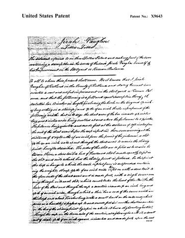
Page 2.
United States Patent
Patent No.: X9643
Jirah Vaughan
Jirah Vaughan
The following is a description of a new and useful improvement in the steel yard or Roman Balance.
It is all to whom these presents shall come. Be it known that I, Jirah Vaughan of Scotland in the County of Fife and Stirling, Scotland, have invented a new and useful improvement in the steel yard or Roman Balance, and that the following is a full and exact description thereof, viz.:
The steel bar is 13 inches in length, including the hook on the long end 17 inches long, setting in a sharp edge, and 1/2 of an inch thick is furnished of the following widths: that is to say, the short arm of the bar is made 4 1/2 inches long and 3 inches wide, being swelled at one end where the fulcrum is 3 1/2 inches. The fulcrum being made and made fast at the distance of 3 1/2 inches from the end of the short arm before the axis is put in, then commencing at the distance of 5 eighths of an inch from the point of the fulcrum, a slit 1/2 of an inch wide is cut through the short arm to receive the sliding joint, hereinafter described. The sides of this slit are so filed as to receive between them a stone tail or bar of brass or steel made equally to fit in the slit, and into which bar the sliding joint is fastened. In this joint the top is hinged to which the scale or plate forms is suspended, containing the weights. A loop of 1/2 of an inch wide is set on with a stone tail to the open ends of the short arm and is made fast, with a single screw running through into each slot, which constitutes the head of the bar. On the line of the bar and through the loop, a mortise is made 1/2 of an inch long and 1/2 of an inch wide, through which a thin bar or rod of the same width and thickness and about 6 inches long, with a small hook on the end, which serves as a handle, is passed up to one end and fastened, another that is mounted in the bar of the sliding joint by a pin on which it has a slight revolving motion, through the loop in the lower end of the mortise, at right angles with it, a small nut of steel, 1/2 of an inch square, is inserted and made fast upon the end.
Page 3.
United States Patent
Patent No.: X9643
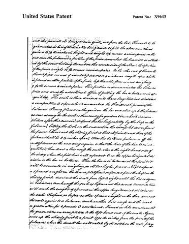
...the thin bar or spring which is attached as just mentioned to the bar of the sliding joint and on the lower edge or side of which bar an adjustable or guiding means equally to set on the cost and so as to maintain the sliding at the several points or positions herein after specified. On the upper side of the said movable spring is indicated a small fast with a small screw, the point of which spring acts upon and keeps down the small bar upon the rest. When the sliding joint, by means of this small bar is drawn out so that its points and those of the fulcrum are 3/4 to the maker of part that one or the other is then adjusted to its lowest point. Again let the points of the joint and fulcrum approach to the distance of 1/16 the maker where the small bar will be with its points not touching the rest. The balance is now prepared to open its second period. When lastly, let the points be moved up to their supreme position, 1/4 from inch, the balance is then prepared to open its highest period, as will be more fully explained hereafter in describing the graduated plane scale. The tongue of the bar or balance is made 1/4 inches inward throughout, specifying a line on the upper and inner sides at the extreme and 1/4 inch square each, to which the image is drawn by its two ends, the lower being produced in the line of the bar and slightly bent at its extreme point, serving to hold in place that end of the bar in a slidable manner from a frame above, and 1/4 inch is thrown through the tongue to a point within 1/4 of an inch of the end. On this side a gain is made, such as is on 1/4 the as an inch deep from a point 1/4 an inch from the fulcrum and through out the length of the arm. As to this gain and equally fitting, it is placed the graduated scale which is made to slide back and forth thereon and is maintained in the gain by the following means: a second paper through at right angles, near the end of the scale near the fulcrum of sufficient length on one side to hold a portion of the joint, and on the other side to pass through the slot in the body above into a nut on the same side, which maintains that end of the scale in the gain, on the end of the body above on the knife above mentioned, a thin and narrow strip of steel passing over that end of the scale is made fast to the knife and is so arranged the image, which maintains the other end of the scale in the gain.
Page 4.
United States Patent
Patent No.: X9643
and also prevents it being drawn quite out from the bar. The scale to be graduated as hereof the division being made to fit the above mentioned grain is 12 ½ inches in length and a weight 11½ ounces a point in the end near the fulcrum a portion of the force somewhat the heaviest is attached by the lower holding the nut on the reverse side of the Bar. This portion of the force weighs 16 ½ ounces a point in force. On the other end of the scale there is fixed an arm of an end of about 3 or 4 inches in length upon which is placed another portion of the force, less than the former and weighing 9 ½ ounces a point in force. This portion is designed to take the balance force and serve the additional office of putting the bar in balance in equilibrium. The scale is then divided into three longitudinal divisions a convenient reference which are marked the three pound forces of the balance. Being placed in the grain on the bar and close up to the fulcrum as near as may be the scale is then ready for graduation which is commenced after the manner described. The bar is held horizontally by the loop on the fulcrum, letting the hook on the end rest in the universal screw found the frame. Draw out the sliding joint so that its points and those of the fulcrum shall be 3 ½ inches apart, turn the balance force on or off the nut as soon as the axis may require so that the line of the bar is in equilibrium; then draw a line along the scale close to the right-hand side of the inner edge of the first line until it represents 1 on the upper horizontal division on the bar in balance. When the bar is in balance at this point it will be accurate in weighing up to two higher forces. Next suspend a 1 pound weight on the three or platform suspension from the loop on the sliding joint, draw out the scale from left to right until the bar is again in balance and mark along the scale as before and this second horizontal line will mark the weighing of 1 pound on the upper longitudinal division on the scale. Next, as before another 1 pound weight on the three, draw out the scale again to a balance, mark another line along, and the mark or graduation for 2 pounds is ascertained. Proceed in like manner until the graduation is complete on the left-hand end of the scale. Again move up the sliding joint to a point 1 ½ inches from the points of the fulcrum, where the small bar will catch by its notch on the rest, place the
Page 5.
United States Patent
Patent No.: X9643
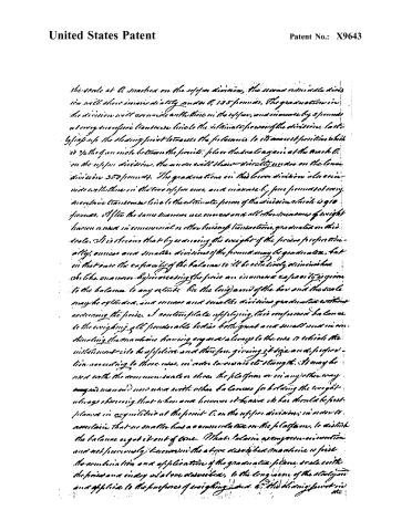
the scale at C, marked on the upper division, the second minute division will show immediately under C, 125 pounds. The graduation in the division will coincide with those in the upper, and increase by 5 pounds at every successive transverse line to the ultimate power of the division, lastly by going up the sliding joint towards the platform, to its lowest position which is 3/4ths of an inch between the pivots, place the scale again at the mark C, on the upper division. The number will show directly under on the lower division 250 pounds. The graduation in this lower division also coincides with those in the two upper ones, and increase by 500 pounds at every successive transverse line to the ultimate power of the division which is 910 pounds. If the same manner we can read all the increments of weight between ounces in commercial or other weighing transactions, graduated on this scale. It is obvious that by assuming the weight of the poise proportionally, ounces and smaller divisions of the pound may be graduated, but in that case the capacity of the balance will be relatively diminished. As like an answer. By increasing the poise an increased capacity is given to the balance to any extent. On the long arm of the bar and the scale may be extended, and ounces and smaller divisions graduated without increasing the poise. I contemplate applying this compound balance to the weighing of all ponderable bodies both great and small and in considering the machine having regard always to the ease to which the instrument is to be applied and therefore giving it size and proportions according to those cases, in order to ensure its strength. It may be used with the common scale or else the platform or in any other way and manner now used with other balances for holding the weight always showing that when one balance is known to be in equilibrium at the point C, on the upper division, in order to ascertain that no smaller has a commensurate on the platform, to disturb the balance or get it out of course. That balance as my own invention and not previously known in the above described machine is first the combination and application of the graduated poise, scale with the point and index as above described, to the long arm of the scale and applied to the purposes of weighing, and at the sliding joint in the
Page 6.
United States Patent
Patent No.: X9643
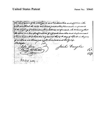
The short name of the electrolyte as above described, and of the cells with or without the said combined graduated planes scale as aforesaid is the weighing of all practicable substances as aforesaid. In testimony that the above is a true specification of my said invention and improvement I have hereunto subscribed my name this 4th day of April in the year of our Lord one thousand eight hundred and thirty-six.
Witnesses
Joseph Gove
Henry W. Porter
Jesse Vaceglove
2040 1071
Published accounts: journal notice
Notice in the monthly list of patents
Journal of the Franklin Institute, new ser., vol. 18 (1836), p. 143 · View the page
335. Balance.-Jirah Vaughan, Rutland, Va.
About this record
- Patentee
- DATAMP
- Date
- the Name and Date index of patents, DATAMP, USPTO records
- Invention
- DATAMP
- Listed in
- the Name and Date index of patents, DATAMP, USPTO records, Jim Shaw's X-patent list, the Journal of the Franklin Institute, Burke's List of Patents (1847)
- The Franklin Institute's journal spells the name differently.
- Burke's 1847 Patent Office list gives the same patent.