

Drawings and documents
National Archives restored drawings: drawing
J. Rouse's Patent Drawing for a Machine for Making Butts and Hinges

National Archives, Restored Patent Drawings (Record Group 241) · Full-size scan at the National Archives · Catalog record
Show the text on the drawing Hide (93 words)
Words on the drawing as machine-read by the National Archives; not checked. Useful mainly for searching.
53. METAL WORKING, / HINGES. / bay / 17 / 9666-4 / 9666X / U.ROUSE / Making Butts & Hinges / may 17-66 / Pull / References. / A. Dive with " circular gronver aftertare to form He / B. and transurs, 07' Follower / e. Frame / D. cams / F Pilinn Shackle-bar with flexible joint / follower G to enter the Die and exper He Hinge / WHITE formed, In nusting it -plt at the opposite end / See August / Made under the direction of the com / in Coi formity with act of 3 d March
USPTO scan
The patent as scanned by the USPTO
-
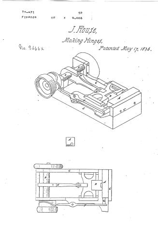 Page 1
-
 Page 2
-
 Page 3
-
 Page 4
-
 Page 5
-
 Page 6
-
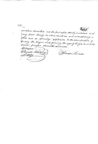 Page 7


U.S. Patent and Trademark Office · Google Patents
Show the transcription Hide (1,988 words)
Machine transcription (LightOnOCR) of the pages as scanned by the USPTO, most of them the handwritten copies made when the records were restored after the 1836 fire. Not checked; it can misread handwriting, so compare it with the scan.
Page 1.
72-421
FIP8009
OR X 9,666
SR
J. Rouse,
Making Hinges,
Patented May 17, 1836.
No. 9,666 x

Page 2.
May 17, 1836.
Patented May 17, 1836.
9666X
84.
Vancas Brouse
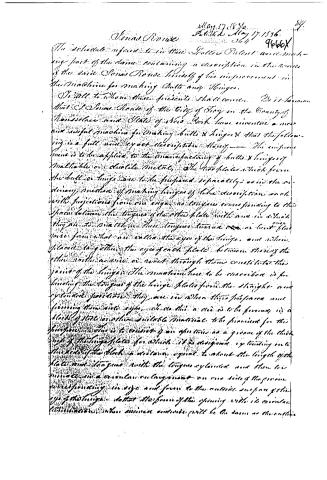
The schedule referred to in this Patent and making part of the same containing a description in the words of the said Vancas Brouse himself of his improvement in the machine for making bolts and hinges.
To all to whom these presents shall come: We it is known that I Vancas Brouse of the City of Troy in the County of Rensselaer and State of New York have invented a new and useful machine for making bolts & hinges & that the following is a full and exact description thereof — The improvement is to be applied to the manufacturing of bolts & hinges of malleable or ductile metals, & the two plates which form the bolt or hinge are to be prepared separately; as in the ordinary method of making hinges of like description each with projections from one edge, so tongues corresponding to the spaces between the tongues of the other plate with one or which they are to be attached. These tongues turn on or least flat surface from what are called the eyes of the hinge, and when placed together, the eyes of each plate between those of the other with a nail or rod through them constitute the joint of the hinge. The machine has to be described is for bending the tongues of the hinge plates from the straight and cylindrical position they are in when their surfaces are pressed into eyes, & so this a die is to be formed in a block of steel or other suitable material to be provided for this purpose. This is to consist of an aperture as a groove of the thickness of the hinge plates for which it is designed, extending into the body of the block a distance equal to about the length of the plate and tongue with the tongues exposed, and then be formed in a circular enlargement on one side of the groove corresponding in size and form to the outside surface of the eye of the hinge. When the force of the opening with its circular termination, when pressed and made, will be the same as the outside
Page 3.
90.
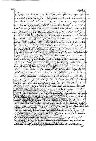
of a file or one side of the hinge plate after the eye is formed, The whole of this opening is to be extended through the entire length of the block. This constitutes the die. And the eyes of the hinge are formed by placing the plate with the tongue extended within the groove near its mouth and forcing the tongue and forward into the circular termination of it. The effect of which will be that as the tongue enters the circle, on the concentric direction of a tangent line from it, the ends are formed round its surface, which for this purpose should be smooth, till the tongue conforming to the curve become but flatwise in their whole length or so as to bring the ends over to their own surface or to that of the plate, to which they belong. To effect this operation a steel follower adapted to the groove and the end of it to the edge of the hinge plate should be provided, and a reciprocating movement given to it sufficient to open and force the piece, the tongue effectively, into the circle and then to return back far enough to allow the hinge plate to be removed and another placed before the follower ready for a like operation. This may be done by fixing the die firmly upon a frame to be provided for the purpose, and running a shaft with a crank or eccentric section to rotate before it, and a hollow or double bar connected therewith and operated to and connected with the follower by a flexible joint, such as is ordinarily applied to operation of that kind, will give the movement required. In such other means or means as are conveniently found for producing movement of the nature, as well as not, whether for effecting the necessary force, as by roller gearing or otherwise may be adopted in this case as shall be deemed expedient. The follower may be supported and kept true in its direction by means of projections running in guides or working from it, horizontally and vertically, as by tongues and grooves or otherwise with the features of the same provided for this purpose.
Page 4.
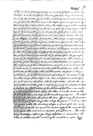
A bar or lever extending along on one side of the frame from near the shaft to a point opposite the end of the disc, may be so connected with the machinery, as to have a lateral movement outwards or inwards to the end except the shaft by means of a crank upon the side of the shaft which turns the shaft or of a shaft or pully connected and revolving with it, so that by suspending or attaching it by a movable joint to a point of the frame provided for the purpose, as its fulcrum at such point between the two ends thereof as shall be selected, the same reciprocating motion will strictly correspond to the end of the disc, when by attaching a follower thereto any tendency towards the end of the disc, and so as to have it move backwards and forwards in the direction of the length of the disc, it may be made to return into its usual position, the hinge plates after the eye or for med by locking it out at the opposite end. The relative position of the crank, which gives the motion, is subject to the movement of the other follower, may be such as to cause the inward and outward motion of the two followers to be in alternate with each other, so that when the first is being withdrawn from the disc and preparing to its return with another hinge plate before it, the other follower will pass in and assume the place which is finished. To also the extent of the motion of the end follower may be adapted to such a purpose by the location of the fulcrum of the lever, as in giving it more or less than the other, as in the extent or the length of the lever or size of the arm may require. To avoid a lever for the above purpose the same effect may be produced by means of a shaft along the side of the frame, to be connected by gears with the revolving shafts in front of the disc and, having a crank or eccentric motion opposite the end of the disc to produce the one and in motion of the followers, the necessary connecting apparatus being affixed at either end. A lever to actuate the return of the end follower after being
Page 5.
92.
This carried into the die by the motion of the lever or of the cam, upon the lateral shaft, a spring may be attached to a fly arm of the frame and thus applied to the lever or an off-ender of it in one side or to one off-ender of the follower in the other, so to replace the follower in its outward position. The instant the operating wind shall have passed the point of its alternate action for propelling it forward, the wind for this purpose should be found within a commutation sufficiently short as to admit of such motion.
This provision is for the purpose of preventing any interference between the followers or large plates within the die, which a slower movement in this particular might occasion, and this is the description of the principle rather than of the proper manner in which the result is to be obtained. Observe its practical application as left as a matter of discretion to be exercised in the construction of this part of the apparatus. By placing a large plate or surface for the die, before the wind follower with the tongue extended in the right direction, the same may be driven in by it sideways and placed in the groove before the other follower ready to be forced into its position. But this plate thus supplied may be made to finish before it, that is to say, its finish and accuracy within the die and so that any wear or before the passage for the entering the other follower. Upon this principle an up-right top or take way is provided and fixed to a hopper before the next follower reaches the die, that is, a series of large plates being placed one after another, and then set with the tongue all on one direction, and the followers are directed towards the die, being made to carry before or with the groove that the large plates are the first and then again drawn back to the other side of the hopper, or any of the pile of plates within the groove. The arrangement will work as soon as the die is arranged forward in the same manner. The hopper in this case should be so constructed as to have a passage from between the followers and the
Page 6.
and the die sufficient for the lower plate to be carried through
the thickness above will be kept in place by the sides of the loop
until the follower is again drawn back from under them.
Or instead of this location for the follower it may be fixed
in front of the die before the other follower so as to turn the
lower hinge carried by it directly into the die with the
longer and faster. While the other follower may as
before be applied to the removing of the plate from the die
than finished. Instead of a die of the foregoing description
one may be made to answer the same purpose by being
divided horizontally into two parts — the division commencing
at or near the back part of the circular termination of
the groove and continuing through to the back side of the block
or of the two pieces which in this case would be substituted for
it. In any other respect the die should be the same as that
above described. In order to keep them firmly together during
the process of forming the eyes of the hinge plate and to assist
the fingers which that shall occasion, an operative
roller should be placed on the loop extending across the
same and secured by journals in fixtures provided therefor
at the ends so that by turning the projecting side of the roller
down upon the upper part of the eye, it will force the jaws to it
and produce the form the same as if it were constructed from
known block, and by turning the roller back after the eye is
formed it will release the plate from the fingers to which
it will necessarily be subjected by the process and allow it
to move readily, smoothly, and this is the purpose of the
lateral divisions. By the improvements thus herein
above specified and described, I claim as my own invention
the manner and principle of turning or bending the longer
of longer butt plates of Malleable or castable metal and
forming them into eyes by forcing them into a die constructed
for that purpose. Also I also claim the manner
Page 7.
144.
as above described and the principles thereby embodied and every part thereof as above combined and as constituting a whole and as specially applicable to the above purpose of bending the tongues and forming the eyes of hinges, and to the several processes therein with connection.
Witnesses
Daniel Whiting
L. Blais
Thomas House
9666X
Published accounts: journal notice
Notice in the monthly list of patents
Journal of the Franklin Institute, new ser., vol. 18 (1836), p. 143 · View the page
364. Butt Hinges. Jonas Rouse, Troy, N. Y.
About this record
- Patentee
- DATAMP
- Date
- the Name and Date index of patents, DATAMP, USPTO records
- Invention
- DATAMP
- Listed in
- the Name and Date index of patents, DATAMP, USPTO records, Jim Shaw's X-patent list, the Journal of the Franklin Institute, Burke's List of Patents (1847)
- Burke's 1847 Patent Office list gives the same patent.