

Drawings and documents
National Archives restored drawings: drawing
Nathan Scholfield's Patent Drawing for a Machine for Regulating Motion

National Archives, Restored Patent Drawings (Record Group 241) · Full-size scan at the National Archives · Catalog record
Show the text on the drawing Hide (20 words)
Words on the drawing as machine-read by the National Archives; not checked. Useful mainly for searching.
86 / To / II / FE / of
USPTO scan
The patent as scanned by the USPTO
-
 Page 1
-
 Page 2
-
 Page 3
-
 Page 4
-
 Page 5


U.S. Patent and Trademark Office · Google Patents
Show the transcription Hide (1,502 words)
Machine transcription (LightOnOCR) of the pages as scanned by the USPTO, most of them the handwritten copies made when the records were restored after the 1836 fire. Not checked; it can misread handwriting, so compare it with the scan.
Page 1.
9667X
N. Scholfield,
Governor.
Patented May 17, 1836.
Fig. 1.
Fig. 2.
Page 2.
$\text{Extended for three years from 17th May 1836}$
$\text{Nathan Scholfield}$
$\text{9667X}$
$\text{The Schedule referred to in these Letters Patent and making part of the same, containing a description in the words of the said Nathan Scholfield himself, of his improvement in the art of regulating the motion of water wheels, steam engines, &c.}$
$\text{To all to whom these presents shall come.}$
$\text{Be it known that I Nathan Scholfield of Norwich in New London County and State of Connecticut have invented a new and useful improvement in the Governor or Regulator for water wheels, steam engines, &c. and that the following is a full and exact description of the construction and operation of the said machine as invented or improved by me. My improvement consists in making such mechanical additions to the common steam engine governor as to cause it to move the gate or valve alternately and in degrees corresponding to the variation of the motion from the true or required velocity, also to cause it when it does move the gate to do so suddenly and then to rest some length of time for the visible effect of such movement before moving it again &c. A.B. Fig. 1st represents a plank which serves as a base or support for the machine and in the one which I shall describe is 28 inches in length 12 inches wide and 1/2 thick. P.O.—A.H.—and S.L are studs or stands bolted to the plank and serving as supports for the governor O.B. and the horizontal shafts a.a and b.b; the shaft a.a being 6 inches and b.b 10 inches above the plank A.B. p is a pulley on the shaft a.a by which the machine is put in motion. ff is a pendulum lever fitting loosely on the shaft b.b as its fulcrum and point of suspension, and it has a reciprocating motion by means of the crank a.d.d., the stud d.d. of the crank moving up and down in the slot in the pendulum (see Fig. 2nd) as the shaft a.a revolves. h.h is a stud made fast to the top of the lever and on which are two hands or dogs o.o which by their reciprocating motion are allowed to move the toothed wheel g alternately, one way or the other as occasion may require, and the toothed wheel g being made fast to the shaft, moves it also,}$
Page 3.
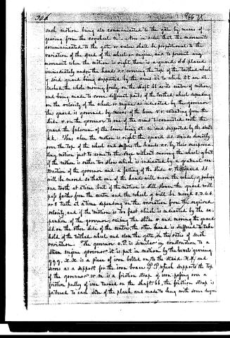
such motion being also communicated to the gate by means of gearing from the cogwheel m... stow in order that the movements communicated to the gate or valve shall be proportional to the variation of the speed of the wheel or engine, and to prevent any movement when the motion is right, there is a guard d d placed immediately under the hands a r. covering the top of the toothed wheel g. said guard being supported by the arms i i to which it are attached, the whole moving freely on the shaft b b as its centre of motion, and being made to cover different parts of the toothed wheel depending on the velocity of the wheel or engine as indicated by the governor, this guard is governed by means of the lever v v extending from the slide o on the governor to one of the arms l connected with the guard the fulcrum of the lever being at w and supported by the studs k k. Thus, when the motion is right the guard d d stands directly over the top of the wheel and suffers the hands a r. by their reciprocating motion just to come to the edge without moving the wheel g but if the motion is rather too slow which is indicated by a gradual contraction of the governor and a falling of the slide o, the guard d d will be moved so that one of the hands will move the wheel g perhaps one tooth at a time but if the motion is still slower the guard will pass farther from the centre and the wheel g will be moved 2, 3, 4, 6, or 8 teeth at a time depending on the variation from the required velocity, and if the motion is too fast which is indicated by the expansion of the governor, raising the slide o and moving the guard d d on the other side of the centre, the other hand is suffered to take hold of the toothed wheel and close the gate in the ratio of such variation. The governor o p is similar in construction to a steam engine governor it is put in motion by the bevel gearing g g g, x x x is a piece of iron bolted on to the stand m m and serves as a support for the iron brace p p which supports the top of the governor. w m is a friction strap of iron passing over a friction pulley of iron turned on the shaft b b, the friction strap is fastened to each side of the plank and made to hang with some degree
Page 4.
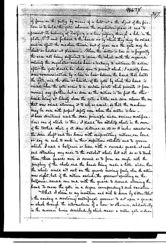
of force on the pulley by means of a bolt at a the object of this friction is to hold the gate whenever the regulator places it and to prevent its moving of itself by a line passing through a hole in the plate P.P. and fastened to the hands or by which they may be raised and in effect the machine thrown out of gear and the gate may be shut or hoisted at pleasure. When the water is low as is frequently the case not being sufficient to drive the wheel with the required velocity the regulator would have a tendency to continue its action after the gate should be clear open to prevent which, I usually have some communication by a line or lever between the hand that hoists the gate, and the stem or handle of the gate by which this hand is raised when the gate comes to a certain point which prevents it from moving any farther, but as soon as the motion is too fast the other hand being at liberty closes the gate a little and soon relieves the one that was raised allowing it to act as usual, so that the machine may be run with perfect safety even when the water is low.
I have sometimes used the same principle under various modifications one of which is this. I placed two ratchet wheels in the room of the toothed wheel g at some distance as 12 or 18 inches asunder on the same shaft and two levers with reciprocating motions, one hand or dog in each to work in their respective ratchets and to govern which I used a balance or lever with a curved guard at each end extending very near to the ratchet wheels but not so as to touch them, these guards were so curved as to form an angle with the periphery of the wheels, and the hands being made a little wider than the wheels would not rest on the guards moving freely when the motion was right, but if the motion varied, the governor operating on the balance, caused one end with the guards to descend allowing the hand to move the gate in a degree corresponding to such variation.
What I claim as my invention and wish to secure by Letters Patent is the causing a revolving centrifugal governor to act upon a guard or check through the intermedium of a lever or otherwise, substantially in the manner herein described, by which means a water gate or steam
Page 5.
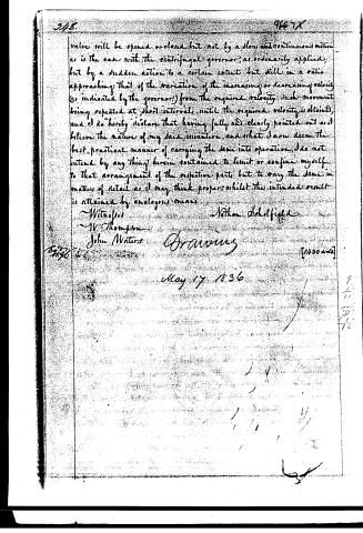
valve will be opened or closed but not by a slow and continuous motion as is the case with the centrifugal governor, as ordinarily applied, but by a sudden action to a certain extent but still in a ratio approaching that of the variation of the increasing or decreasing velocity (as indicated by the governor) from the required velocity. Such movement being repeated at short intervals until the required velocity is obtained, and I do hereby declare that having fully and clearly pointed out and believed the nature of my said invention, and what I now deem the best practical manner of carrying the same into operation, I do not intend by any thing herein contained to limit or confine myself to that arrangement of the respective parts but to any the same in matters of detail as I may think proper, whilst the intended result is attained by analogous means.
Witnesses
W. Thompson
John Waters
Nathan Scholfield
Drawing
May 17, 1836
[1400 words]
Published accounts: journal notice
Notice in the monthly list of patents
Journal of the Franklin Institute, new ser., vol. 18 (1836), p. 143 · View the page
363. Regulating machinery.-Nathan Scholfield, Norwich, Conn.
About this record
- Patentee
- DATAMP
- Date
- the Name and Date index of patents, DATAMP, USPTO records
- Invention
- DATAMP
- Listed in
- the Name and Date index of patents, DATAMP, USPTO records, Jim Shaw's X-patent list, the Journal of the Franklin Institute, Burke's List of Patents (1847)
- Burke's 1847 Patent Office list gives the same patent.