

Drawings and documents
National Archives restored drawings: drawing
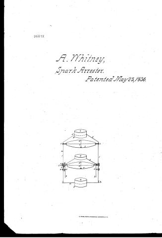
A. Whitney's Patent Drawing for a Spark Extinguisher and Heat Condenser

National Archives, Restored Patent Drawings (Record Group 241) · Full-size scan at the National Archives · Catalog record
Show the text on the drawing Hide (44 words)
Words on the drawing as machine-read by the National Archives; not checked. Useful mainly for searching.
CLASSIF1CAT13 / 9681.4 / Al. o WHITN EYTS / DIVISION. / Spark extinguisher x Heat Condenger. / Patented May nized 1836. / 85 / cl / 95 / to / damper being / plate of thut metal / without holes in in is / 3457 / 36 / 41
USPTO scan
The patent as scanned by the USPTO
-
 Page 1
-
 Page 2
-
 Page 3
-
 Page 4


U.S. Patent and Trademark Office · Google Patents
Show the transcription Hide (1,193 words)
Machine transcription (LightOnOCR) of the pages as scanned by the USPTO, most of them the handwritten copies made when the records were restored after the 1836 fire. Not checked; it can misread handwriting, so compare it with the scan.
Page 1.
9681X
A. Whitney,
Spark Arrester.
Patented May 23, 1836.

Page 2.
May 23, 1836
Abner Whitney Albany N. York
Letters Patent
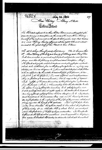
The Schedule referred to in these Letters Patent and making part of the same containing a description in the words of the said Abner Whitney himself of his improvement in the spark Extinguisher and that certain as (said Whitney having assigned all his right title and interest in and to the equal half of this Patent to Love & Bunn.
To all to whom these presents shall come. I do it known that I Abner Whitney of the City and County of Albany and State of New York have invented a new and useful spark extinguisher and heat condenser and that the following is a full and exact description thereof.
The Spark extinguisher and heat condenser made of any proper material which will withstand fire in the form of a cylinder or as nearly as possible (as No 1 on Diagram A) from one end substantial at the bottom with an aperture in the middle to receive the pipe of the furnace below (No 2 & 4) at the top (No 3) it is made elliptical and is so formed something in fashion of a common funnel) that it may enter if required also a pipe of the same dimensions as that placed upon it proceeding from the furnace (No 4). Immediately below the shoulder No 3, where the ellipse begins is placed two iron bars No 5, which pass from side to side and cross each other at right angles in the center (No 5) horizontal iron bars is placed a plate of iron called a damper No 6. This damper must be padlocked to the lowermost bars and yet the lower of the bars are in proportion to the circumference of the pipes of the furnace which must always regulate the height of the cylinder so that if the pipe be ten inches 10 in diameter the cylinder ought to be about the proportion of thirty inches 30 in diameter that is about 3 to 1, and according to what that proportion if the pipes is larger or smaller. The Damper No 6 stand at the top as above mentioned would agreeable to the proportion ought to be about 26 inches in diameter which will have about
Page 3.
118. 9681X
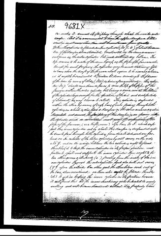
14. makes 2. annular cylinders through which the smoke will congeal. And it is recommended to have the apparatus a little smaller in all dimensions than would be most convenient for apparatus.
Within this cylinder is placed another cylinder (No 7-6) of about the same size of the transverse above described. Constructed in the same manner and form as the outer cylinder but made without any bottoms. The top seems to be made of the same height as the sides of the furnace and though for most purposes the cylinders may be made stationary, yet in cases where the draft of the furnace shall require to be increased a little, it ought to be constructed to be raised or lowered according to the pleasure of the user by means of slides (No. 8) as herein after mentioned. This cylinder (No 7) would come down so far as to cover the top of the pipes of the furnace within the outer cylinder but leaving a space near at the bottom of the cylinder large enough for the operation of the air, and to be partially of sediment as may chance to collect. This cylinder is suspended within the other by means of cross bars of iron passing through both cylinders on a slide is also fixed a transverse in the same manner as above described and around the periphery of this transverse is an opening within this cylinder which on rotation will guard the upper parts of the pipes of the furnace (see figure more). The bars No 5, which support the inner cylinder and by which this transverse is suspended will be easily passed through both cylinders from side to side, and one fastened on the outside of the outer cylinder by nut screws on the ends No 9, and on the inside between the two cylinders ought to be placed thimbles (d) to keep the inner cylinder in its proper position, and further to support and support the inner cylinder. There ought to be two other screws with heads (e) passing from the inside of the inner cylinder through the outer cylinder, these also with nut screws (f) upon the outside one above and the other below each end of the bars, also mentioned, on these also ought to be placed thimbles (d) to aid in keeping the inner cylinder in its position because it will be found that all the inner machinery will be heated to nearly melting and will become distorted without this properly braced.
29
Page 4.
dampers to the shoulder of No 3 steam valves (g). No 3 from the decomposition of matter within the actuating tubes will collect an oxydate sub stances in small particles called culls. They will fall upon the bottom of the cylinder and may be removed by a small door (h) upon each side of the cylinders at the bottom of which may be opened at pleasure whenever this invention is used in open air, but otherwise if used in water. If the operator wishes further to condense heat he may only that he can do it by adding one or more dampers to the inside of the cylinders and also add flanges appended from the cylinders above the flanges. But in all cases likewise intending a flange or object that may bear any other name he must take care to form the throats or apertures for the smoke to pass freely. It must not be understood that the cylindrical shape is supposed to be the only form in which this invention may be made. Any other form that may any object will be of equal utility if the conditions will pay attention to the just proportions of the parts that the shape of the smoke and that the exhausts are not, my invention may not be obstructed within the cylinder. What I claim as my own invention and not previously known is the above detailed machine is the invention construction affording and improving the whole machine as improvement as above set forth for the use and benefit as provided in the said above specifications and to be applied to the pipes of Home stoves to prevent the escape of sparks of fire and to condense and create heat. Also to the pipes of a locomotive fire or engine and to Steam Boats, for the prevention of sparks, also if placed near a furnace where the melting of iron or something requires much of heat this machine will be found highly useful.
In testimony that the above is a true specification of my said improvement as above described I have hereunto set my hand this day of February 1836.
Witness
J.O. Eole
Wm. Robson
D. H. Whitney
1930 1:37
Granted May 23, 1836
Published accounts: journal notice
Notice in the monthly list of patents
Journal of the Franklin Institute, new ser., vol. 18 (1836), p. 143 · View the page
372. Spark extinguisher.-A. Whitney and S. S. Burr, Albany, N. Y.
About this record
- Patentee
- DATAMP
- Date
- the Name and Date index of patents, DATAMP, USPTO records
- Invention
- DATAMP
- Listed in
- the Name and Date index of patents, DATAMP, USPTO records, Jim Shaw's X-patent list, the Journal of the Franklin Institute, Burke's List of Patents (1847)
- Burke's 1847 Patent Office list gives the same patent.