

Drawings and documents
National Archives restored drawings: drawing
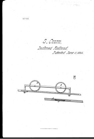
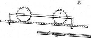
Smith Cram's Patent Drawing for a Rail Road

National Archives, Restored Patent Drawings (Record Group 241) · Full-size scan at the National Archives · Catalog record
Show the text on the drawing Hide (56 words)
Words on the drawing as machine-read by the National Archives; not checked. Useful mainly for searching.
A. RAILWAYS. / 1. THE "WAY." / 120]. Inclined Plancs. / CLASSINICATION / 9710-+ / 9710X / Smith Cram's / Rail Road / Patented June 11 1836 / vol. 26, fa 24th / A. ecpped wheels / B rails and rounds / C vertical Toller / D horizontal wheel / special a -4. / and / il II / 1.
USPTO scan
The patent as scanned by the USPTO
-
 Page 1
-
 Page 2
-
 Page 3


U.S. Patent and Trademark Office · Google Patents
Show the transcription Hide (653 words)
Machine transcription (LightOnOCR) of the pages as scanned by the USPTO, most of them the handwritten copies made when the records were restored after the 1836 fire. Not checked; it can misread handwriting, so compare it with the scan.
Page 1.
9710X
S. Crann,
Inclined Railroad,
Patented June 11, 1836.

THE NORRIS PETERS CO., PHOTO-LITHO., WASHINGTON, D.C.
Page 2.
X9710 June 11, 1866 241
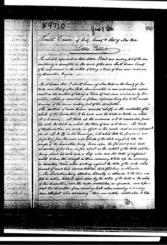
Smith Crane, of Loyal, County & State of New York.
Letter Patent.
The schedule referred to in these Letters Patent and making part of the same containing a description in the words of the said Smith Crane himself of his improvement in the method of taking a train of cars over eminences by locomotive Engines.
Be it known that I, Smith Crane, of New York in the County of New York, and State of New York, have invented a new and useful improvement in the method of taking a train of cars over eminences by locomotive, which is described as follows, reference being had to the accompanying drawings of the same, making part of this specification.
The method of said Crane consists chiefly in the construction of the wheels of the locomotive to be used and the track or tracks on which it is to move. A track up the eminences is to be constructed parallel with the track on which the train of cars is to move. The tracks of the locomotive are made in effect as two racks such as are represented at A & B, in the Drawings, into which teeth C, formed in and projecting from the arms or peripheries of the wheels may freely take the weight of the locomotive being borne upon, the flat part of such racks construction of flat bars, as far apart as the width of the teeth each bar being about one inch and a half wide and the teeth of sufficient width to have the strength in them necessary to take up the ascending or descending train when working against the teeth of the racks, which consist of round bars secured between said flat bars as otherwise.
This locomotive being attached laterally or otherwise to the train and put in motion, takes it up or down by the action of the teeth in the wheels of the locomotive, upon the racks constructed as aforesaid, and to prevent the locomotive from running back when ascending or running down too fast when descending there are catches constructed to take
Page 3.
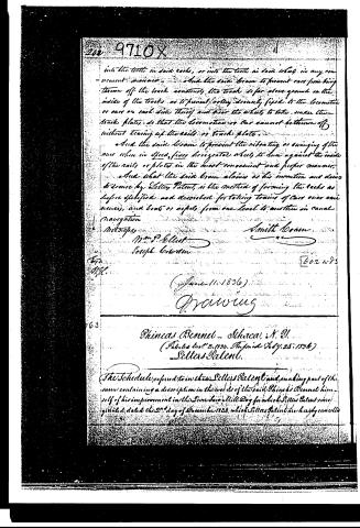
into the teeth in said racks, or into the teeth in said wheels, in any convenient manner. And the said beam to prevent cars from being thrown off the track, construct the track so far above ground on the inside of the tracks as to prevent rolling securely fixed to the locomotive or cars on each side thereof and near the wheels, to take under the tracks plates, so that the locomotive or car cannot be thrown off without tearing up the rails or track plates.
And the said beam to prevent the vibrating or swinging of the cars when in speed, fix horizontal wheels to run against the inside of the rails or plates in the most convenient and proper manner.
And what the said beam claims as his invention and does to secure by Letters Patent, is the method of forming the tracks as before specified and described for taking trains of cars over canals, and boats or vessels from one level to another in canal navigation.
Witnesses,
Smith Brown
Wm. P. Elliott
Joseph Coarden
[602 wds]
(June 11, 1836)
Manning
Phineas Bennet... Schenectady, N.Y.
(Patented Dec. 2, 1834. Reprinted July 25, 1836)
Letters Patent.
The Schedule referred to in these Letters Patent and making part of the same containing a description in the words of the said Phineas Bennet himself of his improvement in the Screw Saw Mill Dog for which Letters Patent were granted, dated the 2nd day of December 1834, which Letters Patent are hereby cancelled.
Published accounts: journal notice
Notice in the monthly list of patents
Journal of the Franklin Institute, new ser., vol. 18 (1836), p. 214 · View the page
386. Cylindrical breaker.-Smith Cram, N. Y.
Published accounts: journal notice
Notice in the monthly list of patents
Journal of the Franklin Institute, new ser., vol. 18 (1836), p. 215 · View the page
402. Cars, taking over elevations. Smith Cram, N. Y.
DATAMP: illustration
Illustrations from DATAMP

DATAMP (Directory of American Tool and Machinery Patents), via the Internet Archive · Archived DATAMP page
About this record
- Patentee
- DATAMP
- Date
- the Name and Date index of patents, DATAMP, USPTO records
- Invention
- DATAMP
- Listed in
- the Name and Date index of patents, DATAMP, USPTO records, Jim Shaw's X-patent list, the Journal of the Franklin Institute, Burke's List of Patents (1847)
- Burke's 1847 Patent Office list gives the same patent.