

Drawings and documents
National Archives restored drawings: drawing
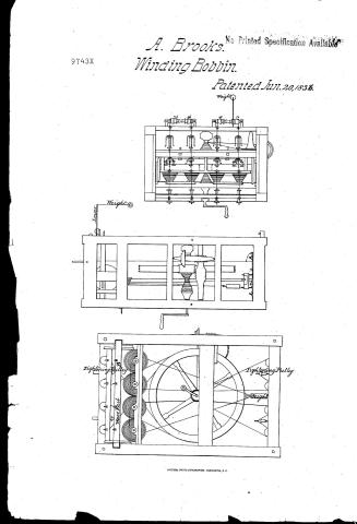
A. Brook's Patent Drawing for a Machine for Winding Cord

National Archives, Restored Patent Drawings (Record Group 241) · Full-size scan at the National Archives · Catalog record
Show the text on the drawing Hide (56 words)
Words on the drawing as machine-read by the National Archives; not checked. Useful mainly for searching.
S. CORDAGE. / [17] Winding Bobbins. / 13 - Covering Cord / Spooding & Reeling - Tex / A. BROOK'S / Juneza 1836 / CLASSIFICATION / Weight / Mouchine for winding bords. / Patented / 9743. X / DIV ISION. / 9743 / If / it / mm / 43 / righting / Tig / Purllary / Puth / Height / 23 / of Weight / 5/21 / 23 / Bobbin screws on specille
USPTO scan
The patent as scanned by the USPTO
-
 Page 1
-
 Page 2
-
 Page 3
-
 Page 4


U.S. Patent and Trademark Office · Google Patents
Show the transcription Hide (1,091 words)
Machine transcription (LightOnOCR) of the pages as scanned by the USPTO, most of them the handwritten copies made when the records were restored after the 1836 fire. Not checked; it can misread handwriting, so compare it with the scan.
Page 1.
A. Brooks.
Winding Bobbin.
Patented Jun. 20, 1836.
No Printed Specification Available
9743X

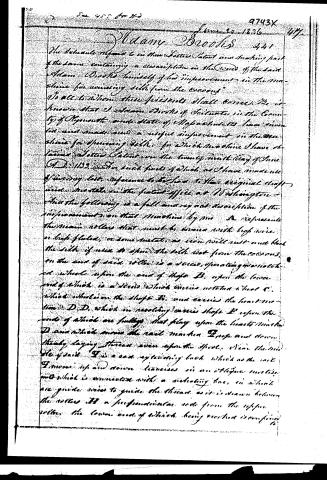
Page 2.
June 10, 1836
Madam Brooks
The detailed reference in this letter Patent and accompanying part of the same containing a description in the words of the said Adam Brooks himself of his "improvement in the machine for unwinding silk from the cocoons."
To all to whom these presents shall come, Be it known that I Adam Brooks of Schenectady in the County of Rensselaer and State of New York have invented and made use of a useful improvement in the machine for unwinding silk, for which machine I have obtained Letters Patent on the twenty-ninth day of June A.D. 1833. For such parts of which as I have made use of in my said improvement I have to this original draft filed a model in the patent office at Washington and that the following is a full and exact description of the improvements on that machine by me. A represents the main rollers that must be driven with high wire or high fluted, or some metal, as iron will suit and that the silk if used to spin the silk not from the cocoons, on the end of such roller is a screw, operating in a notched wheel upon the end of shaft B, upon the lower end of which is a screw which carries notched wheel C, which wheel is on the shaft D, and carries the heart motion D D, which in revolving carries shaft E upon the ends of which are furlongs that play upon the hearts motion D and which moves the reel machine E up and down thereby laying thread even upon the spool. Near the mid of said E is a cast spinning hook which as the reel I move up and down traverses in an elliptic motion and which is connected with a vibrating bar, in which are guides wires to guide the thread as it is drawn between the rollers H a perpendicular rods from the upper roller, the lower end of which being received is confined to
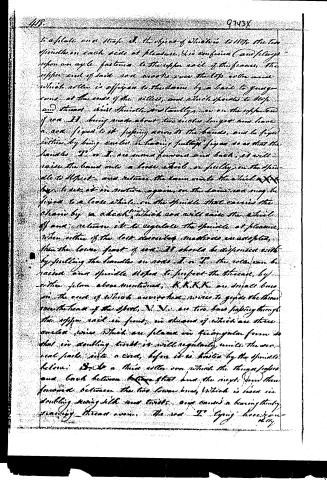
Page 3.
to a plate on a staff. A. the object of which is to stop the two spindles on each side at pleasure. It is confined (and always upon an angle) fastened to the upper rail of the frame. The upper end of said rod works over the top roller which roller is affixed to the beam by a bail to grog-tons at the ends of the rollers, and which grog-tails to stop and thread. Axis Spindle. Distantly, or on the opposite side of rod. II being made about two inches longer and have a axe fixed to it passing across the hands, and to fix position by being curled or having fulltop fixed so as that the hands I. or I. are moved forward and back, it will raise the hand onto a loose wheel or fulcrum on the spindle to adjust, and return the beam onto the wheel. K.K. by which it is motion again on the beam and may be fixed to a loose wheel on the spindle that carries the chain by a check which can will raise the wheel off and return it to regulate the spindle at pleasure. When either of the last described machines are adopted, then the lower part of rod. II should be dispensed with by pulling the handle on rods I. or II. the rods can be raised and spindle stopped to inspect the thread, by either fulcrum above mentioned. K.K.K.K. are small lines on the end of which are no holes, nor vice to guide the thread over the head of the shaft. N.N. are two bars passing through the upper rail in front, in the end of which are three curved wires which are placed in triangular form so that in doubling twist it will regularly unite the several parts into a cord, before it is twisted by the spindle below. D.D. a third roller over which the thread passes and back between before that and the next. From there forward between the two lower bars, which is used in doubling every 4th and twist, and causes a bearing thread passing thread over. The rod II. being here shown.
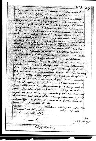
Page 4.
tally is connected to the perpendicular rod which I am also used for stopping the threads at pleasure. B is a tin or cast iron pan with partitions with holes through them for the water to flow equally from one to the other. A.C. are the parts of the pan for the cocons while reciling; I. I. that part of the pan in which to keep the cocons, and to collect the threads to supply when wanting. C.C. represents the room of the furnace which is to heat the water in the pans above, and in which furnace there is a grate within about four inches of the top, and in which furnace can be made wood or coal or any kind by running steam into the pan. A is a pulley upon the end of the cylinder which for common use are to be about four inches diameter, but which may be varied at the taste of the thread required. M is a standing pulley where power is necessary to be applied. N is a loose pulley to stop the machinery at pleasure. P is a belt passing through the upper rail operating through a spiral spring to hold the upper rollers down. Which may be done by the same as a weight. The wings in box D I do not claim to have invented but use them by function of the patentee of this office, but I claim the application of the spindle and wings to spin silk immediately as it comes from the cocons. I have used them & find they will have the greatest speed of any now in use. The above draft and model are designed to be enlarged so as to carry any number of spindles that may be desired and which I have already increased to good advantage, any motor, steam or any other kind of power can be applied to it.
Witness
Samuel S. Stevens
Filed April 4th month 1846
Adam Brooks
Drawings
9743 X 419
164.
[1089]
Published accounts: journal notice
Notice in the monthly list of patents
Journal of the Franklin Institute, new ser., vol. 18 (1836), p. 215 · View the page
442. Winding gimp or cord.-Adam Brooks, South Scituate, Mass.
About this record
- Patentee
- DATAMP
- Date
- the Name and Date index of patents, DATAMP, USPTO records
- Invention
- DATAMP
- Listed in
- the Name and Date index of patents, DATAMP, USPTO records, Jim Shaw's X-patent list, the Journal of the Franklin Institute, Burke's List of Patents (1847)
- Burke's 1847 Patent Office list gives the same patent.