

Drawings and documents
National Archives restored drawings: drawing
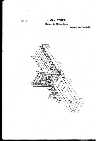
Anson Clark and Charles B. Boynton's Patent Drawing for a Stone Planing Machine

National Archives, Restored Patent Drawings (Record Group 241) · Full-size scan at the National Archives · Catalog record
Show the text on the drawing Hide (181 words)
Words on the drawing as machine-read by the National Archives; not checked. Useful mainly for searching.
125. STONE WORKING, / Dressing / Stone / DIV. 15 / fo / CLASSIFICATION / 9744x / DIVISION / Mone planing Manchine / Patented June 20" 1836. / References. / si / .A. / Foundation timbers. / B. Blatform / C. / Cest iron posts. / D. / Screwn for raising 8 lowering the tool-frame / E. Tool frame / E Cylinder / G lever / Tool block / sliding plates / K. / Screw pa fsing through the tool block / L. / for raising the / M. Rack & pinion / N. 0 Pullies. Cog wheels E / P Clutch / Shifting lever / As / Projecting fins in the side of the pla flatform / T. Clasp. / County of Berkshire / State of Magrachwetts / for On this thirtyfirst tay afitaly 1837 / appeared before the subscriber, a Justice / peace for said County of Bertishire, Anson blark / both of West stockbridge in said County, and mr / they are interested as vaventore in a patent for a Da / sawing machine to them I dated tune 20th 1836 I'm / eng with the references thereto are, as they acrily believe, a / niation of the planing machine and described in wth letters paten. / (Signed) Robbins Kellogg, Instice of ther
USPTO scan
The patent as scanned by the USPTO
-
 Page 1
-
 Page 2
-
 Page 3
-
 Page 4
-
 Page 5


U.S. Patent and Trademark Office · Google Patents
Show the transcription Hide (2,015 words)
Machine transcription (LightOnOCR) of the pages as scanned by the USPTO, most of them the handwritten copies made when the records were restored after the 1836 fire. Not checked; it can misread handwriting, so compare it with the scan.
Page 1.
9744X
CLARK & BOYNTON.
Machine for Planing Stone.
Patented June 20, 1836.
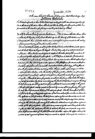
Page 2.
9744X
June 20, 1836
Anson Clark & Charles B. Boynton. West Stockbridge, Mass.
Letters Patent
The Schedule referred to in these Letters Patent and making part of the same containing a description in the words of the said Anson Clark and Charles B. Boynton themselves of their improvement in the machine for planing or cutting and sawing Stone.
To all to whom these presents shall come, "Be it known that We Anson Clark and Charles B. Boynton both of West Stockbridge in the County of Berkshire and State of Massachusetts have invented certain new and useful improvement in the cutting or planing and sawing of Marble & other Stone.
Upon a suitable foundation are placed two sticks of timber about thirteen inches square and at least twice as long as the largest block of stone which is intended to be cut or planed. These timbers are designed to support the other part of the machine & are formed together about five feet apart. A Platform to hold the blocks which are to be planed is formed by bolting planks two or more inches thick upon longitudinal timbers about eight inches square. This platform for common purposes should be about five feet in width and about twelve feet long. It is placed upon the foundation timbers and may slide thereon either upon irons or slides or upon friction rollers. In the centre of the foundation timbers are placed four upright cast iron posts, about seven feet in height & of any required strength. These posts serve for guides in which the frame that holds the tools is moved up and down by screws according as the blocks to be planed vary in thickness. The tool frame is an oblong cast iron frame fitted to move accurately in the guides of the upright posts and is raised or lowered by means of screws passing through the cross bar that connects the tops of the upright posts. On the lower part of this tool frame is hung a horizontal cylinder of cast iron about five inches in diameter. This cylinder or shaft rests on the tool frame upon a journal bearing on each end so as to permit a motion in it, axes and one end of the shaft or cylinder passes through the tool frame far enough to allow the attachment of a lever upon the outside of the upright posts. This cylinder is accurately turned through its whole length so that the cast iron block to which the tools are secured may slide upon it from one side of the platform to the other. Upon the upper side of the cylinder is cut a groove of about half an inch in depth through its whole length.
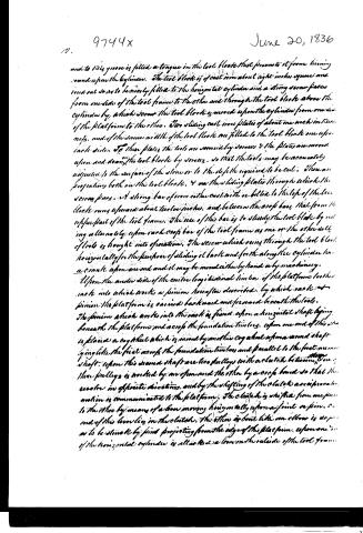
Page 3.
9744x
June 20, 1836
and to this groove is fitted a tongue in the tool block that prevents it from turning round upon the cylinder. The tool block is of cast iron about eight inches square and fixed out so as to be nearly fitted to the horizontal cylinder and a strong screw passes from one side of the tool frame to the other and through the tool block above the cylinder by which screw the tool block is moved upon the cylinder from one side of the platform to the other. Two sliding cast iron plates of about one inch in thickness, and of the same width of the tool block are fitted to the tool block one upon each side. To these plates the tools are secured by screws to the plates are moved upon and down the tool blocks by screws, so that the tools may be accurately adjusted to the surface of the stone or to the depth required to be cut. There are projections both on the tool blocks, and on the sliding plates through which the screws pass. A strong bar of iron either cast with or bolted to the top of the tool blocks runs upward about twelve inches, and between the cross bars that form the upper part of the tool frame. The use of this bar is to steady the tool blade by resting alternately upon each cross bar of the tool frame as one or the other set of tools is brought into operation. The screw which runs through the tool block horizontally for the purpose of sliding it back and forth along the cylinder has a crank upon one end and it may be moved either by hand or by machinery.
Upon the under side of the entire longitudinal timbers of the platform is a rack into which works a pinion hereafter described, by which said pinion the platform is carried backward and forward beneath the tools. The pinion which works into the rack is fixed upon a horizontal shaft lying beneath the platform and across the foundation timbers. Upon one end of this shaft is placed a cog wheel which is moved by another cog wheel upon a second shaft going like the first across the foundation timbers and parallel to the first named shaft. Upon this second shaft are two pulleys with a clutch between them. One of these pulleys is worked by one span and the other by a cross band so that the wheels in opposite directions, and by the shifting of the clutch a reciprocating motion is communicated to the platform. The clutch is shifted from one pulley to the other by means of a lever moving horizontally upon a joint or pivot. One end of this lever lies in the clutch, the other is bent like an elbow is so proportioned as to be struck by pins projecting from the edge of the platform. Upon one end of the horizontal cylinder is attached a lever on the outside of the tool frame.
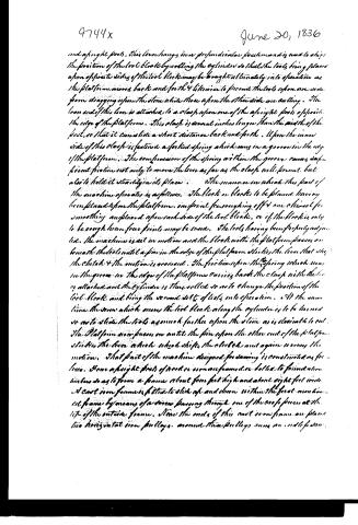
Page 4.
9744x
June 20, 1836
and a right foot. This lever hangs in a perpendicular position and is used to shift the position of the tool block by rolling the cylinder so that the tools being placed upon opposite sides of the tool block may be brought alternately into operation as the platform moves back and forth & likewise to prevent the tools upon one side from dragging upon the stone while those upon the other side are cutting. The lower end of this lever is attached to a clamp upon one of the upright feet opposite the edge of the platform. This clamp is several inches longer than the width of the foot, so that it can slide a short distance back and forth. Upon the inner side of this clamp is fastened a forked spring which runs in a groove in the edge of the platform. The compression of the spring within the groove causes sufficient friction not only to move the lever as far as the clamp will permit, but also to hold it steadily in its place. The manner in which this part of the machine operates is as follows. The block or blocks to be planed, having been placed upon the platform, one point for roughing off & one other for smoothing are placed upon each side of the tool block, or if the block is only to be rough-hewn four points may be used. The tools having been properly adjusted, the machine is set in motion and the block with the platform passes on beneath the tools until a pin in the edge of the platform strikes the lever that shifts the clutch & the motion is reversed. The friction upon the spring which runs in the groove in the edge of the platform carries back the clamp with the lever attached and the cylinder is then rolled so as to change the position of the tool block and bring the second set of tools into operation. At the same time the screw which moves the tool block along the cylinder is to be turned so as to slide the tools as much further upon the stone as is desirable to cut. The platform now passes on until the pin upon the other end of the platform strikes the lever which shifts the clutch and again reverses the motion. That part of the machine designed for drawing is constructed as follows. Have a right foot of wood or iron framed or bolted to foundation timbers so as to form a frame about four feet high and about eight feet wide. A cast iron frame is fitted to slide up and down within the first mentioned frame by means of a screw passing through one of the cross pieces at the top of the outside frame. Near the ends of this cast iron frame are placed two horizontal iron pulleys, around these pulleys runs an endless strap.
Page 5.
9744x
June 20, 1836
...mate of band or hoop iron; upon the upper end of the shaft which passes through one of the pulleys is placed a horizontal cog wheel which works into a vertical wheel, upon the shop of the vertical wheel is a pulley around which a belt passes which drives the machine in operation. This belt also passes around a pulley upon the main shaft of the planing machine. The stone is to be placed between the horizontal pulleys beneath the same. The pressure of the lever upon the stone is regulated by the screw which raises and lowers the former, and the lever is supplied with sand and water as are the saws now in use for the sawing of stone. What is claimed as new in the planing machine is the form of the tool blocks, except the sliding plates; the manner in which it is held firm & steady by the bar which rests against the edge of face of the tool former; the method by which the position of the tool block is altered so as to bring one set of tools into operation and prevent the other from straggling upon the surface of the stone, and the application of the combined and similar to the planing cutting or working of stone. What I claimed as new in that part of the machine for sawing is the application of an iron belt saw to the sawing of stone to be used with sand and water as other saws now are, by which application the advantages of a circular saw machine are obtained without the inconvenience of the common circular saw. The planing machine is applicable not only to the squaring of blocks, the leveling and smoothing of surfaces, but to the rounding and filing of columns, the cutting of grooves and straight moldings for steps, cornices and other similar work. The principal feature of this machine that distinguishes it from Hunter's English stone planing machine is that the English machine, the tool moves on a stationary stone, while in this the stone moves upon a platform against stationary tools. Hunter's tool former moves as if viewed from his platform so that no block with his machine can be planed lengthwise longer than the width of the platform. Many blocks of our marble for building are from one foot to twelve feet long and from twelve inches to fifteen inches square. These cannot be planed as before because the tools would destroy the corners of the blocks, which it is absolutely necessary to preserve. To plan such blocks in a machine of Hunter's form would require a machine so large as to be unworkable and unviable. Hunter's tools can only be raised or lowered a few inches. Our marble blocks vary in thickness from a few inches to several feet, and our tool former rises and falls then or more feet in order to adapt itself to the different thicknesses.
Expt. 1196
Witnesses
Robbin Kellogg
Seth Dickey
Asdon Clark
Charles B. Boynton
(Patented) 20 June 1836
(2016 wms)
Published accounts: journal notice
Notice in the monthly list of patents
Journal of the Franklin Institute, new ser., vol. 18 (1836), p. 215 · View the page
440. Cutting and planing stone.-A.Clark & C.H. Boynton, West Stockbridge, Mass.
About this record
- Patentee
- DATAMP
- Date
- the Name and Date index of patents, DATAMP, USPTO records
- Invention
- DATAMP
- Listed in
- the Name and Date index of patents, DATAMP, USPTO records, Jim Shaw's X-patent list, the Journal of the Franklin Institute, Burke's List of Patents (1847)
- Burke's 1847 Patent Office list gives the same patent.