

Drawings and documents
USPTO scan
The patent as scanned by the USPTO
-
 Page 1
-
 Page 2
-
 Page 3
-
 Page 4
-
 Page 5
-
 Page 6
-
 Page 7
-
 Page 8
-
 Page 9
-
 Page 10
-
 Page 11
-
 Page 12


U.S. Patent and Trademark Office · Google Patents
Show the transcription Hide (3,034 words)
Machine transcription (LightOnOCR) of the pages as scanned by the USPTO, most of them the handwritten copies made when the records were restored after the 1836 fire. Not checked; it can misread handwriting, so compare it with the scan.
Page 2.
United States Patent
Patent No.: X9745
Edward Clark
The Schedule referred to in this Letter Patent, was made a part of the same, containing a description of the works of the said Edward Clark himself, of his improvements in the manufacture of, Metallic salts, usually denominated White or Carbonate of Lead, Carbonate of Copper, acetate of Lead, acetate of copper, & the acetate or per acetate of iron, for which Letters Patent were granted, dated the 4th day of December 1835, which Letters Patent were cancelled, in account of, a defective specification of three Letters Patent granted on the 30 day of July, 1832, which last Letters Patent are hereby cancelled, also, in account of a defective specification.
To all to whom these Presents shall come:
Know ye, that I, Edward Clark, of the town of Lexington, State of New York, & a citizen of the United States, have invented & invented a new and useful improvement in the manufacture of the carbonate of Lead, or White Lead, or of the acetate of Lead, or acetate & acetate of copper, and acetate & per acetate of iron — the process will produce all the above results by merely varying the metal upon to be acted upon, & by varying the relative proportions of the acetic acid or vinegar when the manufacture of the acetates are required, & also by omitting the carbonic acid when the acetate or per acetate of iron is intended to be produced. But the process is principally useful in the manufacture of white Lead, or carbonate of lead, & to that extent, to the manufacture of the sugar or acetate of lead. I have reserved myself in this description — The terms of my said specification for a Patent to be issued in due time, & no more. I hereby surrender.
It being not effecting any improvement in the manufacture of White Lead. I construct a cylindrical vessel of plank, 60 in length, 2 feet in height, & about the same in diameter. Plunged
Page 3.
United States Patent
Patent No.: X9745
should be made light & strong enough to resist some pressure from within. This is called the surrounding chamber or casing. The plug also be made in the form of a box, box, or cylinder, and may be made of any material, such as wood, metal, or leather, and may be of any shape, as the place & quantity of metal to be treated to be operated upon at a time may require. The sheets of lead cast in the usual manner & from, in being supported on wooden rods or sticks which are supported by their round to the inside of the surrounding chamber, & the sheets are placed as closely as they can conveniently be, & not touch each other. The sheets of lead may be rolled & placed on shelves perforated with holes, or upon any kind of slats or with parts, or in vessels containing vinegar, but not in contact with it, or in any other manner so as to expose their surface to the action of the acid vapors & other agents brought to act on them.
The agents & are to contain metallic lead & make the metal take up amounts of lead & white lead, as the vapors of vinegar, vinegar acid gas & oxygen gas, the best of which is contained in sufficient quantity in the atmosphere & these agents are made more nearly specific effective by being mixed & used in greater quantities or proportions than they have heretofore been applied to the same purpose, in the same form of lead, & by means of all which I propose to make & useful results.
To avoid the expense of vinegar it is to fill the surrounding casing & to incorporate sheets of lead with it in the most effective manner as any object; & this I accomplish in various ways, without being able to give a limited preference to either.
Results. I put the vinegar into copper stills, as shown at E fig 1. of the annexed drawing; & then by applying heat to the furnace below, generate the vapors of vinegar, which pass from the stills into the pipe, & and thence along with the other agents into the branch pipes. (A, B, C, and D) & stop cocks (F, G) into
Page 4.
United States Patent
Patent No.: X9745
the condensing chambers A, B, C, D, E, F, G, H, I, J, K, L, M, N, O, P, Q, R, S, T, U, V, W, X, Y, Z, shown also in Fig. 1. When the method is applied to the condensing agents, pass from the branch pipes H, I, J, K, L, M, N, O, P, Q, R, S, T, U, V, W, X, Y, Z, into the long boxes of three or four inches deep & breadth, which are placed on the sides of the chambers, & are perforated in their sides with a number of small holes for the more equal distribution of the condensing agents.
Secondly, add vinegar or acid into the chambers, & plug the pipes also into the bottom of the condensing chambers, and then which is fed a leaden pipe, which communicates with the steam generator, shown at C, D, E, F, G, H, I, J, K, L, M, N, O, P, Q, R, S, T, U, V, W, X, Y, Z, are passed over a more time and the bottom of the trays according to the quantity of acid vapor required to condense the metal added, as the most efficient manner.
Thirdly, if but vinegar in vessels, & at a short distance above it, & place coils of metal, & filling any condensing chambers with these coils, introduce the carbonic acid gas & atmosphere air heated to such a temperature as to produce the rapid evaporation of the vinegar — or possibly, & place a tube on the outside of the condensing chambers, which is furnished with a charging, discharging & vapour pipe, each supplied by a stop cock. One of these pipes is for the vinegar & water into the tubes, and is for the vapor to flow. If the time is to condense the steam from it, & communicate the vapor to the condensing chambers, for the evaporation of the vinegar. This pipe is connected into a tube or packing box with the condensing chambers, & a pipe, which contains the vinegar, is inserted & cooled at pressure. If is there, from a condensing part of the condensing chamber, taken out like a tube or packing. And the pipes should be furnished with stop cocks to regulate the supply of water & may pass the time. Sometimes cocks or other contrivances are used to ascertain the depth or quantity of vinegar which the trays, & all shells, & chambers may contain. The quantity of carbonic acid gas necessarily to be introduced into the condensing chambers upon each. This coal is used for
Page 5.
United States Patent
Patent No.: X9745
*leaking) the (pungy) I take this gas by means of the induction pipe to the (blowing) apparatus from the furnace of the brick or stib; & where coal is not used. I take it from a small furnace built for the purpose, in which anthracite coal or wood is burned expressly for the generation of this gas. A view of this pipe is shown at B, fig. 1, and a sectional view at D, fig. 3, of the annexed Drawing. The quantity of atmosphere and oxygen gas which is contained in it, is more considerable than that of the carbonic gas (by) in the proportion of the to one, and I obtain this also the branch pipes so situated in the pipe as shown at F, fig. 1, and at G, fig. 3, or from an aperture at or near the top of the furnace, which I have for the purpose. The introduction of an excess of the (smoking) agents, into the smoking chamber is of no material consequence, because they pass off thru the branch pipes shown at R, R, in the pipe I and those into the other chambers successively until they become so quite expended.
*Connected with the (rapid supply) of oxygen gas) is an (inducing) oxygen gas & carbonic acid gas to the smoking chamber is a gas blowing apparatus, which receives the gases above named in the manner before described & from them into the smoking chambers. These chambers hold the carbonic acid gas & the vapor of wood must be provided within the smoking chambers. For the purpose of introducing these gases into the smoking chambers I have made use of the common (Scheuchzer) bellows & by driving the hand so that the bottom of the chamber (and) was made to pass thru a (tight) furnace containing (solid) coal & then furnish the carbonic acid gas, while the other supply the required quantity of oxygen gas. I have also used the (coplan) bellows which is constructed by placing two (united) (solid) (to) (with) (con) (lamin) (weld) & furnished with induction & induction union in pipes, which were made to feed the required supply of
Page 6.
United States Patent
Patent No.: X9745
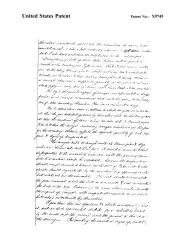
The above mentioned parts are the same as the ones described in the preceding patent, and are not described in detail here. The same is true for the parts which are not specifically mentioned in this description.
The description of the parts of the apparatus will be found in the drawings accompanying this patent. The drawings are not to scale, but are intended to show the relative positions of the parts.
The apparatus is designed to be used in the production of sugar from cane. The cane is first crushed and then passed through a series of rollers to remove the juice. The juice is then heated and evaporated to produce a syrup. The syrup is then cooled and crystallized to produce sugar.
Page 7.
United States Patent
Patent No.: X9745
the acetate of copper, it is only necessary when the acid of copper
become converted, to shut off the gas, increase the acid vapors
until the acetates which have been previously formed are
converted into acetates & then evaporating the liquor which
remains in the condensing chamber.
The washing the lead acetate or acetate of iron the paper
of vinegar and nitrosphene are only to be admitted to the quan-
tity of the latter must be particularly regarded, while the acid of iron
held in solution by the acid will be precipitated. When formed
this material should then be put into some oxides, & to keep
left required for use.
The carbonate of copper is made in precisely the same way
as the carbonate of lead, but its conversion from the metallic
state, being much more slow & difficult, than that of lead;
it is found expedient to conduct this process by applying the
warmly expanded residue of the acid condensing chamber to it.
Where the condensing agents are too abundantly supplied,
placed as the preceding chart of the gas distributed, and at R.
fig 7. into containing about half the number of flasks on the
inside and upper part of the condensing chamber & connect
it by the branch pipe R to the pipe & fig. 1 which leads to
& discharges itself into one or more chambers in succession which
are supplied with stock lead or copper, with a (pipe of strong)
the inside of the condensing agents should any have escaped
the first application. The blowing cylinder is made sim-
ilar to the cylinder of a steam engine with the valves, must
engaged & it may be put into operation, by a tube, steam, or
natural power.
The improvement consists in applying the com-
bined means before described & all other substantially the
same process may be arranged for forcing oxygen gas &
carbonic acid gas, either pure or in a state of combination
with other substances into chambers or vessels heated or not)
Page 8.
United States Patent
Patent No.: X9745
heated which have previously been furnished with casings or sheets of lead or copper according to the method designed to be asst. no. (Therefore claim no. 1) invention the plan of forming atmosphere into close tight, & strong, (including) chambers and connected with carbonic acid gas to the vapour of vinegar & increasing them acted by active and heat, pressure, & motion, by which the corroding agents are first put into close contact with the sheets of lead or copper, and are made to act more vigorously than in any other way heretofore known & practiced — all as shown in with such other, & with the above described corroding chambers, vats, troughs, boxes, boilers, & apparatus for conducting & forcing the agents for corroding the lead or copper, with the corroding chambers in the manner above described or in any other manner substantially the same. The accompanying drawing will further illustrate my specification.
Witnesses
for A. Bicknell & Co.
P. Curtis.
Description of the annexed drawings—fig. 1 represents a series of corroding vessels with a blowing apparatus for supplying them with atmospheric air, carbonic acid gas, & the vapour of vinegar. Fig. 2 represents the corroding vessels & chambers. 3. The blowing cylinder & apparatus & the still or copper boiler containing vinegar. 4. The furnace for heating the vinegar & also for supplying carbonic acid gas to the blower pipe for supplying the blowing apparatus with carbonic acid gas from the furnace. 5. An aperture to admit a supply of atmospheric air into the blowing cylinder thru the pipes 3. 6. The reducing pipe for conducting the carbonic acid gas, the atmospheric air, & the vapour of vinegar into
Page 9.
United States Patent
Patent No.: X9745
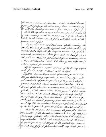
the corroding cisterns or chambers. H. H. &c. the lateral branch pipes for supplying the distributing boxes located at B. &c. Fig II, with the corroding materials from the main pipe G. H. H. the stop cocks to regulate the admission or exclusion of the corroding materials at the pleasure of the attendant. H. H. &c. the suction branch pipes, with their cocks, to the main suction pipe.
Fig. II, represents an interior view of the corroding cisterns or chambers, partially supplied with their castings of metallic lead, disposed for corrosion in various ways. H. H. represents two chambers lined from B. &c. the boxes perforated with small holes for distributing the corroding materials in the chambers. C. D. & E. sheets of lead suspended or fixed as exposed for corrosion.
Fig. III represents a sectional view of the burning apparatus, formed as shown, as shown within in Fig I.
Fig. IV, representing a series of corroding cisterns with the gas distributing apparatus as described in Fig. I, with an additional apparatus for heating the gases (also for generating the said steam within the chambers. A. &c. A view of the chambers or corroding cisterns. B the burning cylinder. C the steam boiler. D the furnace. E. &. &c. main steam pipe. F. & G. branch steam pipes leading from F, through the troughs F, in the chambers. F. & G. the ends of the troughs as shown projecting from the corroding cisterns. In A. Fig. VII for receiving the vapors which is to be heated by the steam pipes & there the apparatus there shown at F.
H. H. &c. the pipes for conveying the gases thru the heat of chambers of the furnace as shown at B. &c. Fig VIII from the burning cylinder, thru the branch pipes H. &c. to the corroding cisterns. I. & J. the lateral branches of the main gas pipe for conveying the gas to the distributing boxes as seen at B. &c. Fig. J. & K. furnished with stop cocks the same
Page 10.
United States Patent
Patent No.: X9745
as thrown in the steam pipes. In the smoke pipe, Fig. V. Two of the chambers open to view. A.A. the two chambers (conducing) A.B. troughs for containing vinegar (for distributing) the gases. D.D. the rods or (laths) for supporting sheets of acid. E.E. the sheets of lead suspended over the acid.
Fig. VI. is a vertical section of one of the chambers with its door removed. A.A. etc. the rods or laths for supporting the sheet of lead. (b) the trough for containing the vinegar. C.C. the gas distributing box.
Fig. VII. a ground view of one of the chambers with its trough, box & pipes. A is the trough for containing vinegar. B. the steam pipe running into the vinegar trough. C. the pipe for conveying off the waste steam or condensed vapors. D.D. stop cocks for regulating the supply of the condensing material. E. the gas distributing box. F. the branch of the main pipe connected with the distributing box.
Fig. VIII. is a sectional view of the blowing cylinder (c) chamber, for heating the gases. A represents the piston head & rod of the cylinder. B.B. the induction valves. C.C. the suction valves. D. the induction pipe for supplying carbonic acid gas from the furnace & air from the aperture shown at D. E. the aperture for admitting air or pieces, etc. F. the suction pipe which conveys the gas from the blowing cylinder to the heated chamber. G.G. a tube for converting water into steam & heating the vinegar in the trough. H. the furnace. I.I. the smoke pipe. K.K. the chamber for heating the gases in their passage into the pipe. L. the heated tube the interior of pipe heating from the heated gas. M. chamber for the conveyance of the heated gases as above described.
[3208 12578]
Page 11.
United States Patent
Patent No.: X9745
E. Clark,
Manufacture of White Lead.
Reissued June 20, 1856.
Sheet 1 & Sheet 2

Fig. 1
Fig. 2
Fig. 3
Fig. 4
Page 12.
United States Patent
Patent No.: X9745
Sheet 2 - 2 Sheets
E. Clark,
Manufacture of White Lead,
Reissued June 20, 1836.

Published accounts: journal notice
Notice in the monthly list of patents
Journal of the Franklin Institute, new ser., vol. 18 (1836), p. 215 · View the page
439. White lead, &c.-Edward Clark, Saugerties, N. Y.
About this record
- Patentee
- DATAMP
- Date
- the Name and Date index of patents, DATAMP, USPTO records
- Invention
- DATAMP
- Listed in
- the Name and Date index of patents, DATAMP, USPTO records, Jim Shaw's X-patent list, the Journal of the Franklin Institute, Burke's List of Patents (1847)
- Burke's 1847 Patent Office list gives the same patent.