

Drawings and documents
National Archives restored drawings: drawing
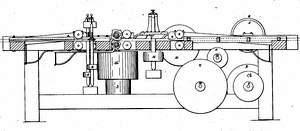
P.M. Martz's Patent Drawing for a Planing, Tonguing, and Grooving Machine

National Archives, Restored Patent Drawings (Record Group 241) · Full-size scan at the National Archives · Catalog record
Show the text on the drawing Hide (61 words)
Words on the drawing as machine-read by the National Archives; not checked. Useful mainly for searching.
42 / 144 WOOD-WORKING MACHINES. / S. / Planing and Matching. / P.M. MARTZ'S / classini 1110 / 9772.X / Planing Tongueing is Grooving machine / Sumber / DIVI IONJ. / 9772X / Patented June / Ap / board / board / 11 / 15 / Board enters / Board discharged / 16 / 10 / Explanatory / Eig. 2 motion to 3. 3à / gires motion to 7.7. / 8 sires motion TO 9. /0 turns 11. og / iilllill / inches / feer
USPTO scan
The patent as scanned by the USPTO
-
 Page 1
-
 Page 2
-
 Page 3
-
 Page 4


U.S. Patent and Trademark Office · Google Patents
Show the transcription Hide (979 words)
Machine transcription (LightOnOCR) of the pages as scanned by the USPTO, most of them the handwritten copies made when the records were restored after the 1836 fire. Not checked; it can misread handwriting, so compare it with the scan.
Page 1.
9772X
P. M. Martz,
Planing and Matching Machine.
Patented June 25, 1836.

A.M. PHOTO-LITHO. CO. N.Y. (OSBORNE'S PROCESS)
Page 2.
June 25, 1846
P. M. Marty, of the Borough of Indianapolis, Indiana.
Letters Patent.
The schedule referred to in these Letters Patent was making part of the same containing a description in the words of the said P. M. Marty himself of his improvement in the machine for planing, tangling and grooving flooring plank.
To all to whom these presents shall come,
Be it known that I P. M. Marty, of the Borough of Indianapolis in the county of Marion and State of Indiana, have invented a new and useful Planing Mill for the purpose of Planing, Tangling, and Grooving Flooring Planks and that the following is a full and exact description thereof.
Frame 12 feet long, 8 feet 4 inches high, 4 feet 6 inches wide, all made of scantling 5 by 8 inch, framed with tenons and mortises and made fast by iron bolts or keys. The ground pulley or band wheel marked at 1 on its profile, being 15 inches in diameter, and is made fast on the one end of an iron shaft 16 feet 6 inches long 1 1/2 inch square and lays horizontal across the lower part of the frame near the one end.
The said pulley or band wheel being propelled by band from either steam, water, or horse power. Pulley or band wheel No. 2, being fast on same shaft and is 22 inches in diameter and by band gives motion …
Page 3.
to the centre and gives motion to No. 3 & on same shaft and is 20 inches in diameter and by band gives motion to 2 pulleys or bands wheels No. 4 and 1 No. 16. Pulley or band wheel No. 7 being 5 inches in diameter are made fast on 2 iron shafts 4 feet 6 inches long 1 1/2 inches in diameter and lay horizontal across the top of the frame immediately over each other, on which shafts knives or cutters are made fast, which work the tongue and make straight the other edge of the board prepared for the groove to be cut therein. These cutters are made fast by screws and tops prepared to be set for wide and narrow boards. Pulley or band wheel No. 4 being 5 inches in diameter and made fast on 2 iron shafts 2 feet 6 inches long 1 1/2 inches square and stands vertical at the edge of each board, on same shaft the cutters are made fast by screws and tops and makes the groove into the edge of each board. Pulley or band wheel No. 16 being 10 inches in diameter, and is made fast on a cast iron shaft 2 feet 8 inches long and 2 inches in diameter, and stands vertical within 18 inches of the one edge of the frame and opposite to the centre on which shaft there is a cast iron drum made fast which has 4 arms on which arms are made fast by screw bolts 4 knives or cutters 8 inches long and stand 2 inches down, the lower edge of the knives being laid with steel and made sharp to plane the boards, as they pass through between the edge of the cutters and the frame. The vertical shaft on which the knives or cutters are made fast stands with the lower end in a step or a bridge-tie. That by keys the same may be raised or lowered according to the thickness of the boards, which the knives or cutters are to plane. The upper end of said shaft is made fast by box and binder on an upright arch made of cast iron extending across over the frame, each end made fast on each edge of the frame by screw bolts. Two boards pass on the top of the frame under the knives or cutting ones on each side of the vertical shaft. The knives or cutters marked No. 16 plane the boards to a thickness as they pass. The cutters on the shaft on which the band wheel No. 7 and No. 4 are made fast they make the tongue and groove as they pass. The boards are put into motion by rollers made of wood and iron shaft.
Page 4.
expanding through them on which shafts are made fast 3 band wheels No. 13, No. 14, and No. 15. Pulley or band wheel No. 9, being 28 inches in diameter and is made fast on an iron shaft 4 feet 6 inches long and lays horizontal across the frame and gives motion to No. 10 on same shaft being 5 inches in diameter and by band gives motion to No. 11. Pulley or band wheel No. 11 being 10 inches in diameter and is made fast on an iron shaft 4 feet long 1 1/2 inches square and lays horizontal across the frame and gives motion to 2 wheels No. 12 being 4 inches in diameter and by bands gives motion to 2 wheels No. 13, being 20 inches in diameter and gives motion to No. 14, being 20 inches in diameter and by band gives motion to No. 15 being 20 inches in diameter and made fast on the iron shafts expanding through the rollers made wood 4 inches in diameter iron pins fast therein and gives motion to 2 boards that the machine is then of operating. The two boards enter at the one end of the machine on the top of the frame and pass to the other end where they will be discharged and the operation of the machine had upon them, they are both made smooth, made to a width and to a thickness and are in full readiness to be laid down into a floor. The bearings are kept to their place by slides and rollers thereon. No. 13, Band wheel marked No. 3 1/2 and 16 see on the longitudinal section of the machine.
August 19th A.D. 1838
Witnesses:
Geo. L. Hinman
H. Crawford
P. M. Martz
1305 nb
Published accounts: journal notice
Notice in the monthly list of patents
Journal of the Franklin Institute, new ser., vol. 18 (1836), p. 287 · View the page
465. Planing machine.—P. M. Martz, Marion county, Ind.
DATAMP: illustration
Illustrations from DATAMP

DATAMP (Directory of American Tool and Machinery Patents), via the Internet Archive · Archived DATAMP page
About this record
- Patentee
- DATAMP
- Date
- the Name and Date index of patents, DATAMP, USPTO records
- Invention
- DATAMP
- Listed in
- the Name and Date index of patents, DATAMP, USPTO records, Jim Shaw's X-patent list, the Journal of the Franklin Institute, Burke's List of Patents (1847)
- The Franklin Institute's journal spells the name differently.
- Burke's 1847 Patent Office list gives the same patent.