

Drawings and documents
National Archives restored drawings: drawing
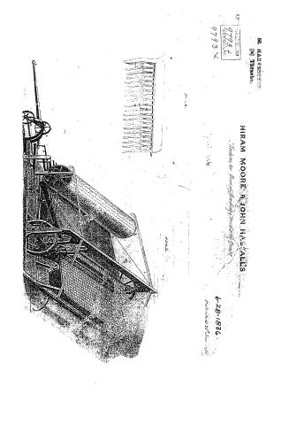
Hiram Moore and John Hascall's Patent Drawing for a Machine for Mowing, Threshing, and Winnowing Grain

National Archives, Restored Patent Drawings (Record Group 241) · Full-size scan at the National Archives · Catalog record
Show the text on the drawing Hide (32 words)
Words on the drawing as machine-read by the National Archives; not checked. Useful mainly for searching.
56. HARVESTERS / [74] Thrashe: / HIRAM MOORE 8 JOHN HASCALL'S / 1.450 / HON / 9793. + / Maduino for. Murringithretings minowing Graing / DIVISION / 9793 X / plast
USPTO scan
The patent as scanned by the USPTO
-
 Page 1
-
 Page 2
-
 Page 3
-
 Page 4
-
 Page 5
-
 Page 6


U.S. Patent and Trademark Office · Google Patents
Show the transcription Hide (1,850 words)
Machine transcription (LightOnOCR) of the pages as scanned by the USPTO, most of them the handwritten copies made when the records were restored after the 1836 fire. Not checked; it can misread handwriting, so compare it with the scan.
Page 1.
56. HARVESTERS
[74] Thrasher.
HIRAM MOORE & JOHN HASSALLS
Machine for Harvesting & Thrashing Crops
9793+
9793 X
6-28-1836.
Patented 28 June 1836
Page 2.
9793 X 6-28-1836 1
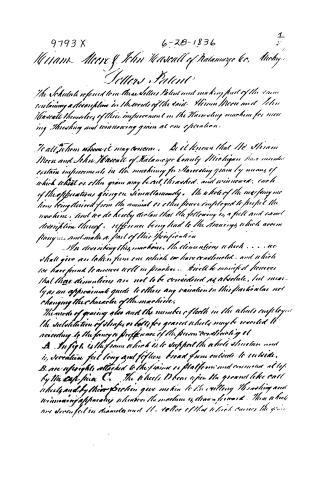
William Moore & John Harsall of Kalamazoo Co. Mich.
Letters, Patent
The Schedule referred to in these letters Patent and making part of the same containing a description in the words of the said William Moore and John Harsall themselves of their improvement in the Harvesting machine for reaping, threshing and winnowing grain at one operation.
To all to whom it may concern, Be it known that We William Moore and John Harsall of Kalamazoo County Michigan have invented certain improvements in the machinery for Harvesting grain by means of which wheat or other grain may be cut, threshed, and winnowed, each of the operations going on simultaneously. The whole of the necessary motions being derived from the animal or other power employed to propel the machine, and we do hereby declare that the following is a full and exact description thereof, reference being had to the Drawings which accompany and make a part of this Specification.
In describing this machine, the dimensions which . . . we shall give are taken from one which we have constructed, and which we have found to answer well in practice. It will be manifest however that these dimensions are not to be considered as absolute, but merely as an approximate guide to others any variation in this particular not changing the character of the machine.
The mode of graining also and the number of teeth in the wheels employed the substitution of straps or belts for gear wheels may be resorted to according to the fancy or preference of the person constructing it.
A. In fig. 1 is the frame which is to support the whole structure and is seventeen feet long and fifteen broad from outside to outside.
B. are uprights attached to the frame or platform and connected at top by the Cross piece C.
The wheels D bear upon the ground like cart wheels and by their friction give motion to the rolling threshing and winnowing apparatus wherever the machine is drawn forward. These wheels are seven feet in diameter and 11.5 feet of that which carries the grain.
Page 3.
9793X 6-28-1836 2.
240.
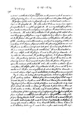
is broad and should it be found to slide on the ground is to be armed with spikes projecting from its rim which will prevent this from taking place. The guide of this wheel is fixed firmly in its link and revolves on braces on the uprights B. The other wheel D turns on an iron axle firmly attached to one of the uprights B. B is a cog wheel four feet in diameter, four inches in thickness and gears into a pinion b' about eleven inches in diameter. The wheel b' is attached to the spokes of the wheel D and the guide of the pinion may be supported by a stud or brace attached to the frame through the intermediate of this pinion the other part of the machinery receives their motions, and as it is necessary to allow the machines to be drawn forward while the operating parts are at rest this pinion is thrown out of and into gear by means of a forked lever C in a manner well known to machinists. H is a band wheel on the same shaft with the pinion b' and is three feet in diameter. I is what we denominate the gathering cylinder to be presently described. This gathering cylinder is turned by a band H as seen in the drawing which band must be crooked when the pinion b' is geared upon the outside of the wheel B when the machine is drawn by manual power the shaft or pole being attached to the frame at K is connected with the four revolving wheels L about ten feet in diameter on a small slider or slide may be substituted for these for convenience.
Fig 2. shows the cutting part of the apparatus which in fig 1 is hidden by the gathering cylinder. M.M. are pieces denominated fingers which may be of wood two feet in length one inch thick and three or four inches deep. They project from the front of the platform and are pointed so as readily to admit the stalks or stems of the grain to pass between them into the cutter or cutters. The cutter may be made as follows. There may be a fixed plate of steel extending along and projecting from the front of the platform or frame immediately under through or on top of the inner ends of the fingers having pointed teeth, resembling saw teeth with a second steel plate furnished with similar teeth made to revolve longitudinally in the former by means of a crank or otherwise so as to cut the stalks or stems between the or the vibrating teeth may be made to turn on pins individually like scissor
Page 4.
9793X 6-28-1836 3. 24.
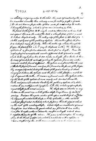
one holding rod giving motion to the whole. This mode of constructing the cutter somewhat resembles those already in use for cutting grass or grain. We do not hereon prefer either of these modes for constructing the cutter believing the following, which is of our own invention, is better.
The fixed toothed plate N N may be made as close or free with saw teeth and against this near the roots of the teeth a straight plate of steel is made to vibrate longitudinally. The cutting edge of this plate is like that of a sickle, and by aid of the gathering cylinder this cutter affects the grass more intended very perfectly. When the sickle edge vibrates through the fingers the fixed plate a b c d may be dispensed with. The gathering cylinder I is four feet in diameter, twelve feet in length. From the surface project a considerable number of pointed teeth of wood or metal which teeth may be from two to six inches in length, from twelve to twenty rows of such teeth extending along the cylinder four or six inches asunder will be found sufficient. The cylinder is so placed that the ends of the teeth project forward, nearly as far forward as the points of the fingers they consequently catch hold of the heads of the grain bending it down carrying it between the cylinder and the front of the platform and holding it against the cutter. A concave is formed under this cylinder allowing the teeth of the cylinder to come nearly into contact therewith.
As the cut grain is conducted back by the gathering cylinder it is delivered on to an endless revolving apron C O. This revolving apron passes round shafts in the usual manner. The shafts are constructed as may be seen in the model one in both of them shafts being driven by suitable gearing. To insure the regular motion of the apron and to keep it in place its edges are furnished with straps or belts of leather or other suitable material perforated with holes which pass over the teeth of guide wheels on the end of the revolving shafts, which shafts are constructed of round bars of iron and between the guide wheels are fitted with loose rollers from four to eight inches in diameter, one foot in length which serve to regulate the centre of the apron. The grain is carried upon the revolving apron to the threshing apparatus which is constructed with a cylinder or cylinders coupled together with conveyors constructed in the usual manner.
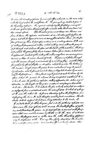
Page 5.
9793X 6-28-1836 4.
We drive the threshing cylinder by means of a spur wheel A on the same shaft with the land wheel B, and pinion C. The gearing being such as to give to the threshing cylinder the required velocity, say the stripping moving at the rate of about five thousand feet per minute when the horses travel at their usual speed. The threshed grain and straw are thrown out from between the cylinder and concave at an elevation of forty-five degrees and strike against a cross screening placed above them, for the purpose of causing them to fall upon a sieve or a revolving screen RR made of rolling fapping around rollers, which rolling screen allows the grain to fall through and delivers the straw at the back of the machine, the trough into which the grain falls has a concave bottom for a reason which will be apparent, instead of the rolling the rollers may have numerous grooves turned in them to receive bands of rods. The grain as it falls through into the concave trough is winnowed by a revolving fan, and the shaft furnished by spiral flights or strainers, which turn near the bottom of the concave trough carries the grain to one end where it may be raised by elevators and be poured out into boxes or bags to be loaded by an assistant on the platform. These parts may be geared so as to be driven by the spur wheel A, as will be obvious to any competent machinist R is a lever to raise the gathering cylinder striking apparatus &c. when any elevation or the height of the grain renders it necessary or desirable to do so. The timber S to which the four wheels and pole are attached is separate from and extends under the main frame to which it is hinged at K near the wheel D. A person standing upon the platform and depressing the lever R will therefore raise the parts mentioned, the stand stands which support its fulcrum being attached to the timber S.
If suitable teeth for threshing are put into the gathering cylinder and the concave the said cylinder will answer the double purpose of gathering and threshing the grain, or if said cylinder is covered with flaps or rather sheet iron and its concave is shielded with the same it will also answer the purpose, and in either case the other threshing apparatus may be suspended with. Having thus fully described the construction and operation of our said machine We do hereby declare that
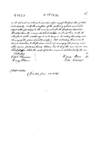
Page 6.
9793 X 6-28-1836 5.
we do not yet claim to invention upon any of the parts thereof taken individually, with the exception of the gathering cylinder and scissor edged roller operating in the manner and for the purposes described. We also claim the manner in which we have combined them with the other parts of the machinery so as to carry on the cutting threshing and cleaning of the grain simultaneously.) Not intending however to limit ourselves to the precise manner of arranging the gearing and other minor parts as herein shown but to vary the same as we may think proper while the mode of action remains substantially the same.
Witnesses
Calit Sherman
Henry Moore
Hiram Moore
John Hascall
(1849 Words) (Granted June 28, 1836)
Published accounts: journal notice
Notice in the monthly list of patents
Journal of the Franklin Institute, new ser., vol. 18 (1836), p. 287 · View the page
483. Harvesting machine.-H. Moore and J. Hascall, Kalamanzo, Mich.
About this record
- Patentee
- DATAMP
- Date
- the Name and Date index of patents, DATAMP, USPTO records
- Invention
- DATAMP
- Listed in
- the Name and Date index of patents, DATAMP, USPTO records, Jim Shaw's X-patent list, the Journal of the Franklin Institute, Burke's List of Patents (1847)
- Burke's 1847 Patent Office list gives the same patent.