

Drawings and documents
National Archives restored drawings: drawing
John Hopper and Andrew Douty's Patent Drawing for a Machine for Hulling Clover Seed

National Archives, Restored Patent Drawings (Record Group 241) · Full-size scan at the National Archives · Catalog record
Show the text on the drawing Hide (43 words)
Words on the drawing as machine-read by the National Archives; not checked. Useful mainly for searching.
the / 130. THRASHING. / 159] Clover Hullers. / youn / 9810.X / DIVISION / Healing Class sad / 9810 X / Patented June 30. 1836. / co / Fipure / Figure 2. / 16 / Figure. % / Oc / c@ / co / 1) / Oc / c@ / co / Fipure 3. / Figure / Tigure 8 / Figure 6.
USPTO scan
The patent as scanned by the USPTO
-
 Page 1
-
 Page 2
-
 Page 3
-
 Page 4
-
 Page 5
-
 Page 6
-
 Page 7


U.S. Patent and Trademark Office · Google Patents
Show the transcription Hide (2,326 words)
Machine transcription (LightOnOCR) of the pages as scanned by the USPTO, most of them the handwritten copies made when the records were restored after the 1836 fire. Not checked; it can misread handwriting, so compare it with the scan.
Page 1.
9810X
Hopner & Denty:
Clover Huller.
Patented Jun. 30, 1836
<!-- Image content: Technical drawings labeled Fig. 1 through Fig. 8, depicting mechanical components of a "Clover Huller" device. -->
Fig. 1
Fig. 2
Fig. 3
Fig. 4
Fig. 5
Fig. 6
Fig. 7
Fig. 8
Page 2.
June 30, 1836 9810X 20
John Hooper & Andrew Doughty, of Moresburgh
State of Pennsylvania
Letters Patent
The schedule referred to in their Letters Patent as making part of the same, containing a description on the work of the said John Hooper & Andrew Doughty themselves of their improvement in the Machine for Hauling Clover Seed —
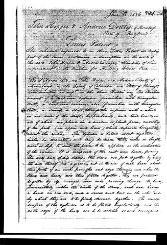
Be it known that we John Hooper and Andrew Doughty of Moresburgh in the County of Columbia and State of Pennsylvania have invented an improvement in the "Clover Hauler" and this Machine consists of a cast iron cylinder, furnished with triangular teeth, a cast iron concave, also furnished with triangular teeth, a socket, a shaft, through the cylinder with a wheel on one end of the shaft, hopperboards, and tailboards, all of which are placed on a wooden or plank frame, consisting of two parts (an upper and lower) which separate horizontally about the center. The cylinder is hollow about eighteen inches in diameter, and may be made thirty inches in length, more or less, to suit the power to be applied or the inclination of the ground. It is composed of two cast iron heads, forming the ends and of six staves, the staves are put together by setting the ends thereof into a groove, cut in the rim of each head about three fourths of an inch from the outer edge thereof, and when the staves and heads are thus fitted together, they are fastened together by six wrought iron rods passing through the heads, immediately within the circle of the staves; each rod having a head on one end, and a screw and bear on the other end, by which they are to be firmly screwed together. The concave surface of the cylinder is to be fitted longitudinally, and the outer edges of the heads are to be notched so as to correspond.
Page 3.
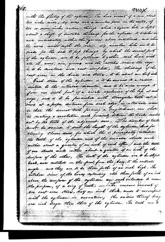
with the fluting of the cylinder. The head consists of a rim about two inches wide, six arms, and a circular piece in the center, of two or more inches radius, through which a square hole is left to admit a shaft of suitable thickness for the cylinder to revolve on and immediately within the grooves above mentioned, and when the arms unite with the rim, six circular holes are to be made for the rods to pass through by which the several parts of the cylinder are to be fastened together, each head with all its arms, rim, grooves and the notches around the cage is to be moulded and cast complete. The thickness of the cast iron, in the heads and stays, is to be about an half inch.
Each stay of the cylinder is to be curved to a radius equal to the internal diameter, and to be wide enough to form one sixth part of a circle exclusive of the lap at each edge; and is to be furnished with triangular teeth set in rows at a proper distance from each edge, in alternate rows so that the several teeth forming a longitudinal row shall in making a revolution, work precisely between the tracks made out by the teeth of the adjacent row. The number of teeth must be varied to suit the length of the cylinder, and for cleaning closer seed, for which this is principally intended the teeth of the cylinder and of the concave should work within about a quarter of an inch of each other, and the teeth of one should work within about a quarter of an inch of the surface of the other. The teeth of the cylinder are to be sloped back, and notched on the front, from the base to the vertical angle, and they are to be three fourths of an inch high. The notched rims of the heavy expanding and three fourths of an inch above the surface of the cylinder are each intended to answer the purpose, of a ring of teeth. The concave consists of two cast iron stays, half an inch thick, made to correspond with the cylinder in curvature, the radius thereof being one inch longer than that of the cylinder. The teeth are to
Page 4.
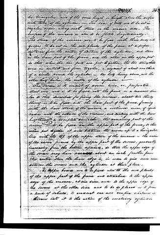
be triangular and of the same length or length above the surface with those of the cylinder. The rows of teeth are to be set in regular order along each stave on the concave side. The surface of the concave is also to be fluted longitudinally. The staves of the concave are to be fixed with their ends into grooves to be cut in the two flanks of the frame, at a proper distance from the centre of motion of the cylinder, one stave in the lower part of the frame, and the other in the upper part so that when the two parts are put together, the two staves come in contact and form together, a segment of about one third of a circle round the cylinder — one half being above, and the other half below, the centre of the cylinder.
The screw is to consist of iron wire, or perforated sheet iron, and is to be fixed into the frame in a manner similar to that described for fixing the concave, about two thirds thereof is to be fixed into the lower part of the frame, forming with the lower stave of the concave, a continued curve, of equal radius with the outside of the concave, and making with the lower half thereof a complete semicircle. The remaining part of the screw is to be fixed in the upper part of the frame, so that when put together it will continue the curve up to a horizontal line with the top of the upper stave of the concave — the radius of the curve formed by the upper part of the screw, gradually increasing from the bottom upwards, so that the upper edge of the screw may have reached about an inch further from the centre than the lower edge is, in order to give more room between the screw and the cylinder at that place.
The upper boards are to be fixed also to the two flanks of the upper part of the frame and attached to the upper edge of the concave, at one side, and to the upper edge of the screw at the other side and to be so placed as to form a kind of shelter, to conduct one and confine whatever is thrown into it to the action of the revolving cylinder.
Page 5.
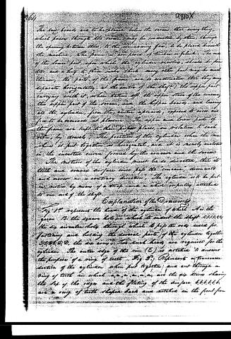
The side boards are to be placed below the screen that everything which passes through the screen may be conducted by them, through the opening between them, to the winnowing fan, to be placed beneath the machine. The frame is composed of timbers or planks. The one of the lower part upon which the cylinder revolves, should be from two and a half to three inches thick, every other part may be much thinner. The parts of the frame are so constructed that they may separate horizontally at the centre of the shaft; the upper part carrying with it, when taken off, the upper stave of the concave, the upper part of the screen, and the upper boards, and leaving all the cylinder, from the centre upwards, exposed to view and free to be removed at pleasure. The upper and lower parts of the frame are kept to their proper places, in relation to each other, by dowels. The position of the cylinder when the machine is put together is horizontal, and it is nearly enclosed in the inverted curve formed by the concave and the screen.
The motion of the cylinder must be so directed, that its teeth and convex surface only pass the "concave," downwards and never in a contrary direction. The cylinder is to be put in motion by means of a strap and a wheel or pulley attached to one end of the shaft.
Explanation of the Drawings
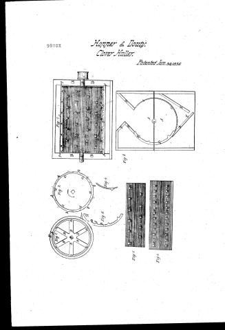
Fig 1 represents the head of the cylinder, of which A is the groove, B the square hole in which to insert the shaft c,c,c,c,c,c, the six circular holes through which to pass the rods used for fastening and holding the several parts of the cylinder together. D,D,D,D,D,D, the six arms. Two such heads are required for the cylinder. The outer edge of the rim (E) is notched to answer the purpose of a ring of teeth. Fig 2 represents a transverse section of the cylinder when put together, and cut through a ring of teeth in which a,a,a,a,a,a are the six staves showing the top of the cogs and the flatting of the surface. b,b,b,b,b,b are a ring of teeth shaped back and notched in the front from
Page 6.
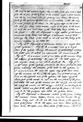
the base to the vertical angle; they are three fourths of an inch in length from the surface of the cylinder to the vertical angle or point ccccc, are the six iron pins used for fastening and holding the several parts of the cylinder together and are immediately within the ring or circle formed by the staves. A, the square shaft in the center. The next (c) shows what direction ought to be given to the motion to suit the cut and shape of the teeth they being notched on the front. Fig. 3. Represents a cross section of the concave composed of the staves cut through a transverse row of teeth showing the shape of the teeth as at A, and the fitting of the concave surface as at V.V.B. &c.
Fig. 4. Represents a transverse section of a single stave of the cylinder. Fig. 5 Is a concave view of a single stave of the cylinder showing the manner of distributing or placing the teeth upon it which are represented at a,a,a,a,a,a,a, &c. Fig. 6. Is a concave view of one stave of the concave showing the manner of distributing the upon it. The teeth appear in two regular rows, as at a,a,a,a,a,a,a, &c. Fig. 7. Is a top view of the cylinder placed in the lower part of the frame, exhibiting the situation of the teeth on the cylinder, as at a,a,a,a,a,a,a, &c. and the upper edge of the lower staves of the concave at b) with the upper row of teeth at cccc, &c. and on the opposite side of the cylinder, the upper edge of the lower part of the concave x, c.c. are the two blanks of the frame into which the ends of the concave are let at f,f, and into which the ends of the screen are let at g,g. - h,h,h,h,h, are notches for the dowels which are fast to the upper part of the frame - i the wheel and k, k, the quaggers upon which the cylinder turns.
Fig. 8. Represents a transverse section of the frame including the concave, screen, hopper, boards, and tail boards, the cylinders being out. a, a, are the side boards of the upper and part of the frame b, b, the upper and lower staves of the concave C, C, the upper and lower parts of the screen - D, D, D
Page 7.
the hopper being to be the tail boards, & the opening through which every thing passes through the screen is connected to the winnowing fan beneath the machine and to a hole in the end for a pulley of the shaft to work in. When the cylinder is placed in as at fig. 7th and the upper part of the frame is put on, as at fig 8th the machine is prepared for use.
The manner of using the mill or machine. When the machine is prepared as above described it is then applied to the hulling of Clover seed only, a quick revolving motion being communicated to the cylinder by means of a strap and wheel as aforesaid, the hopper is to be filled with the chaff containing the seed, which must then be permitted to remain until it becomes fine enough to pass, (chaff and all) through the screen, as it drops through the opening between the tail boards to the fan. The operation is attended with no further trouble than that of keeping the hopper filled, and the process of hulling will be entirely performed by the operation of the machine. In order to adapt it to the hulling or threshing of other seed or grain, the upper part of the cone and the whole of the screen must be removed.
What we claim as our invention is the manner of constructing the cylinder, (as we are aware that cylinders have been long in use, but not constructed after the manner of ours) We therefore claim the method of fluting the circumference, and the outer edge or periphery of the head.
Secondly, the manner of securing the blades and heads together by means of the wrought iron rods as described.
Lastly, the manner of combining the sloped and notched teeth with the fluted cylinder as set forth above.
In testifying that the above is a full and accurate description of our improvement as understood by us we have hereunto set our hands,
Victor Dania Petrikim
Sophia Sholes
John Hopper
Susan Danty.
Published accounts: journal notice
Notice in the monthly list of patents
Journal of the Franklin Institute, new ser., vol. 18 (1836), p. 287 · View the page
495. Clover seed, hulling.-J. Hopper and A. Douty, Moresborough, Penn.
About this record
- Patentee
- Jim Shaw's X-patent list
- Date
- the Name and Date index of patents, USPTO records, Jim Shaw's X-patent list
- Invention
- the Name and Date index of patents
- Listed in
- the Name and Date index of patents, USPTO records, Jim Shaw's X-patent list, the Journal of the Franklin Institute, Burke's List of Patents (1847)
- The Franklin Institute's journal gives a different date.
- Burke's 1847 Patent Office list gives the same patent.