

Drawings and documents
National Archives restored drawings: drawing
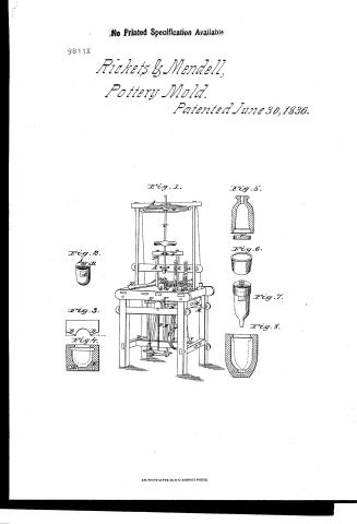
R.B. Ricket and J.C. Mendell's Patent Drawing for a Moulding Machine

National Archives, Restored Patent Drawings (Record Group 241) · Full-size scan at the National Archives · Catalog record
Show the text on the drawing Hide (60 words)
Words on the drawing as machine-read by the National Archives; not checked. Useful mainly for searching.
25, GLAY & POTTERY, / Pottory Machines / Ricketts / 2020 / 25thval with / f2 / R.B.RICKETS / of 1836 for MKS. / DN. 15 / CLASSIFICATION / and / 9811.+ / C.MENDELL'S / DIVICION / Dee / 9811 / 25th Vilience / Priented Trene 304 1836. Restons Patent / 25b 1836 / p.485 / by be / Patented: June 30-1836 / Tig. 1 / Fig 5. / FQ / His 6. / Fig7 / Fig. 8. / 1904 / OF OF
USPTO scan
The patent as scanned by the USPTO
-
 Page 1
-
 Page 2
-
 Page 3
-
 Page 4
-
 Page 5


U.S. Patent and Trademark Office · Google Patents
Show the transcription Hide (1,402 words)
Machine transcription (LightOnOCR) of the pages as scanned by the USPTO, most of them the handwritten copies made when the records were restored after the 1836 fire. Not checked; it can misread handwriting, so compare it with the scan.
Page 1.
No Printed Specification Available
9811X
Rickets & Mendell,
Pottery Mold.
Patented June 30, 1836.
Fig. 1.
Fig. 2.
Fig. 3.
Fig. 4.
Fig. 5.
Fig. 6.
Fig. 7.
Fig. 8.
A.M. PHOTO-LITHO. CO. N.Y. (OSBORNE'S PROCESS)
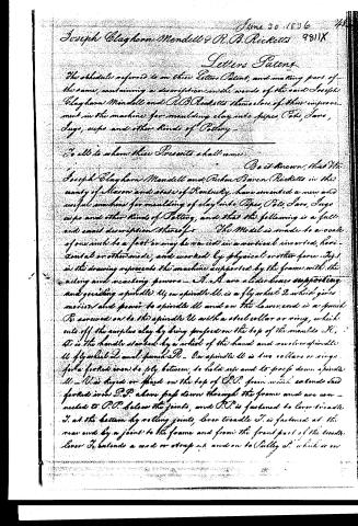
Page 2.
June 20, 1836
Joseph Clayborn Mendell & R.B. Ricketts 9811X
Letters Patent
The schedule referred to in these Letters Patent, and making part of the same, containing a description in the words of the said Joseph Clayborn Mendell and R.B. Ricketts themselves of their improvement in the machine for moulding clay into pipes, Pots, Jars, Jugs, cups and other kinds of Pottery.
To all to whom these Presents shall come:
Be it known, that We Joseph Clayborn Mendell and Rulon Baren Ricketts in the county of Mason and state of Kentucky have invented a new and useful machine for moulding of clay into Pipes, Pots, Jars, Jugs, cups and other kinds of Pottery, and that the following is a full and exact description thereof.
The Model is made to a scale of one inch to a foot, may be varied in a vertical inverted, horizontal or other mode, and worked by physical or other force. Fig. 1 in the drawing represents the machine supported by the frame with the acting and reacting powers. A. A. are a side boxes supporting and guiding spindle U, on spindle U is a fly wheel 2 which gives motion and power to spindle U and on the lower end is a punch P, screwed on to the spindle U with a steel collar or ring, which cuts off the surplus clay by being pressed on the top of the moulds K. D is the handle started by a wheel of the hand and moves spindle U flywheel 2 and punch P. On spindle U is two collars or rings for a forked iron to ply between, to hold up and to press down spindle U. V is keyed or fixed on the top of P.P. from which extends said forked iron P.P. above pass down through the frame and are connected to P.P. below the joints, and P.P. is fastened to lever treadle J. at the bottom by rolling joints, lever treadle J. is fastened at the rear end by a joint to the frame and from the front part of the treadle lever J. extends a cord or strap up and on to Pulley P. which is on
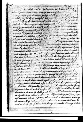
Page 3.
a rotating roller shaft with two other pulleys on the same shaft from the rear pulley winds a cord or strap down and fastened to spring D winding reversely to the one on pulley F. The cord or strap is wound on to the pulley F by the spring D, and from the rear pulley by the same spring D, lifting of lever handle J. The third cord or strap extends from the middle pulley on said rotating roller shaft, down and under pulley G, up and out to a double pulley on spindle I, and from said double pulley extends the fourth cord or strap down and under fast to spring G, reversely to the third cord or strap on said double pulley on spindle I. The lower or left end of spindle I punches the hole for the pipe stem on which there is a steel collar or ring to cut off the surplus clay at the other end of spindle I is a groove for a forked lever I to pry in, which holds spindle I while in its action and reaction, forked lever I is framed into rotating roller H, which is supported by two movable brackets and screws A, A. H is a lever framed into rotating roller H. I and G are fastened into roller H with keys so as to be moveable. I is fastened to lever G at the top by a screw forming a joint and at the lower end to D on the left by a pin forming a joint. X, X are two screws supporting I, I on which are two keys and levers for guiding and supporting spindle I. B, B are the clamps on which the moulds H are fastened with screws L, L. The rear clamp B is fastened with a hinge to the frame at the lower end and opened with a spring on the left side. The front clamp B is fastened at the top and bottom to the frame. Lever O is fastened to the frame on the right, and on the left to lever E forming joints at both ends. Lever E is fastened by a joint to the frame in the rear. The moulds H are closed and wedged together by pressing down lever E, which wedges lever O between a block and the rear clamp B, and by lifting up lever E, the moulds are opened by the spring above mentioned. For moulding pots, jars, jugs, cups and other kinds of pottery, the spindle I is not wanted, and may be taken off by taking out a pin where I is connected to D, and the cord or strap off of the middle pulley, the moulds H may be taken
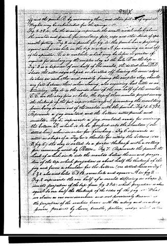
Page 4.
off and the punch A by unscrewing them, and others put on if required. Strights may be substituted for the springs - C.
Fig. 2. 394. In the drawing represents the small model which shows the moulds and punch for moulding pots, cups and other kinds of open-mouth pottery. Fig. 2 is a punch for fig. 1. This punch has a projecting square and a cross hole on the top marked A for screwing on and off of the spindle. B is a vent hole which may be less or greater if required for discharging the surplus clay at the hole B on the top - Fig. 3 is a diagram of one half of the mould, the dotted lines D D shows the outer edges sloped or bevelled off leaving the inner edges to close on each other and readily freeing the surplus clay, should any fall between them when closing, also requiring but little or no trimming. Fig. 4 is the inside view of the one half of the moulds. C. C. are the stay pins or holes, the tops of these moulds project inward the thickness of the pot, cup or other vessel, preventing the moulding from being drawn out of the moulds with the punch - Fig. 5. 6. 7. 8. Represents a jug moulded, and the bottom cutter punch and moulds - Fig. 5. represents a jug moulded ready for receiving the bottom F, which is to be forced into the shoulder (see dotted line) when an order for finishing - Fig. 6 represents an cutter in shape of a Taylor's thimble for cutting the bottoms (see Fig. 5) the clay is rolled to a proper thickness with a rolling pin commonly used by Potter - Fig. 7. Represents the punch the head of which sinks into the moulds below the inward projection of the top which projection is about half the thickness of the jug and forms a shoulder for the bottom (see dotted lines in Fig. 5 & 8. also vent holes C. D. E. some hole and square A in fig 2 - Fig. 8 represents the one half of a mould differing in shape & inward projection of the top from fig. 5 & 4, which projection is about equal to one half the thickness of the sides of the jug - What we claim as our own invention and not previously known is the projection of the machine frame with the rolling and working powers, produced by lever, trundle, friction, wedge, wheel, etc.
Page 5.
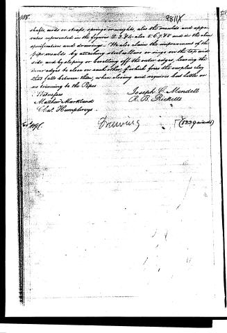
shafts, cords or straps, springs or weights, also the moulds and apparatus represented in the figures 2, 3, 4, also 5, 6, 7, 8 and in the above specification and drawings. I also claim the improvement of the pipe moulds, by attaching steel collars or rings on the top and side, and by sloping or beveling off the outer edges, leaving the inner edges to close on each other, which frees the surplus clay that falls between them, when closing and requires but little or no trimming to the Pipes.
Witnesses
Matthew Hartland
Chas. Humphreys
Joseph C. Mendell
R. B. Ricketts
for N.Y.C.
Drawing (1399 words)
Published accounts: journal notice
Notice in the monthly list of patents
Journal of the Franklin Institute, new ser., vol. 18 (1836), p. 287 · View the page
496. Pottery, moulding.-J. C. Mendell and R. B. Ricketts, Maysville, Ky.
About this record
- Patentee
- Jim Shaw's X-patent list
- Date
- the Name and Date index of patents, USPTO records, Jim Shaw's X-patent list
- Invention
- the Name and Date index of patents
- Listed in
- the Name and Date index of patents, USPTO records, Jim Shaw's X-patent list, the Journal of the Franklin Institute, Burke's List of Patents (1847)
- The residence comes from the Franklin Institute's journal.
- Burke's 1847 Patent Office list gives the same patent.