

Drawings and documents
National Archives restored drawings: drawing
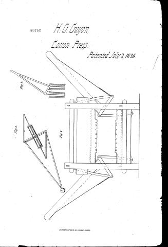
Henry G. Guyon's Patent Drawing for a Compound Lever Press

National Archives, Restored Patent Drawings (Record Group 241) · Full-size scan at the National Archives · Catalog record
Show the text on the drawing Hide (189 words)
Words on the drawing as machine-read by the National Archives; not checked. Useful mainly for searching.
12) Explana tion to NES- / Read 8 / 100. PRESSES. / Baling, / Suppose the bilender a Elivald at bow Toggle-Joint. / Henry Gguyon's Compound Lever Prep fo the / b the Moving fulmon transvers morning on its / Center around on on both sides of the Cilender / Noscinution / the Lever with d the Pendalum attached / Patented 2 July 1836 / st. which the whole is operate by Changing / the Moving fulnour b hanallel to the Cilendera / consequently the lever Bass being attached to the / NE3 / ulinimum and histon and grade by the Juice frame / Condence. the Steam A to the Center - / CLASS IGATION / 9876.7 / 9876 / of Pumps. / E] / N=1 Sideview of Model (Cotton Prip of ress / Standing at about 45day. to opin raise leven him / sction A vire versa / pendicular, and to C lose to Horizontal Po / No1, Side of Collon Prors. / NE2 section of two Pumps worked altimably / with whight Lever as represented / to I propose lifting vessels from the water by Phacing OF Sunderent number of livins acting as lower Part of Prefs / Divor Water Ablinable to 1 / WE3 Represents bilender his Condenn
USPTO scan
The patent as scanned by the USPTO
-
 Page 1
-
 Page 2
-
 Page 3
-
 Page 4
-
 Page 5


U.S. Patent and Trademark Office · Google Patents
Show the transcription Hide (1,291 words)
Machine transcription (LightOnOCR) of the pages as scanned by the USPTO, most of them the handwritten copies made when the records were restored after the 1836 fire. Not checked; it can misread handwriting, so compare it with the scan.
Page 1.
9876X
H. G. Guyon
Cotton Press.
Patented July 2, 1836.
Fig. 2.
Fig. 3.
Fig. 1.
AM. PHOTO-LITHO. CO. N.Y. (OSBORNE'S PROCESS)
Page 2.
9876x
July 2, 1836
Henry G. Guyon : New York City
Letters Patent
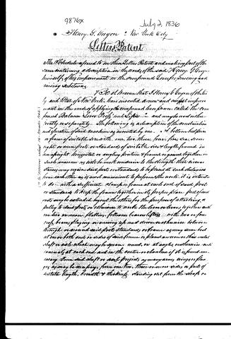
The Schedule referred to in these Letters Patent and making part of the same containing a description in the words of the said Henry G. Guyon himself of his improvement in the compound Lever for lowering and raising substances.
I do declare that I, Henry G. Guyon of the City and State of New York, have invented a new and useful improvement in the mode of applying the compound lever known called the compound Balance Lever, Cross and Sifter — and may be used either jointly or separately. The following is a description of the construction and operation of said machine as mounted by me. A bottom bed piece or frame of suitable size with one, two, three, four, five, six, seven, eight or more feet or standards of suitable size & length framed in an upright horizontal or angling position & framed or joined together in such manner as will be most convenient to the strength that distances may require said feet or standards to be placed at such distances from each other as is most convenient to perform the work; it is intended to be with a sufficient planing frame at each end of said feet or standards to keep the frame together in its proper place. Parts of said feet may be extended beyond the others for the purpose of attaching a pulley to said feet or otherwise to work the lever or levers together with one, two or more platforms, followers, beam lifting with two or four cross beams playing or moving up and down or otherwise between through or around said feet, standards, or frame as may seem best at once both ends or ends of said frame or placed anywhere on their metal shaft or axle which may be square, round, or at angles or otherwise with bearings at each end and in the center or elsewhere if it is found necessary. From said shaft or axle projects as many arms, wings or flanges as may be necessary from one to three or more sides or parts of suitable length, breadth & thickness standing out from the shaft or
Page 3.
9876x
July 2, 1836
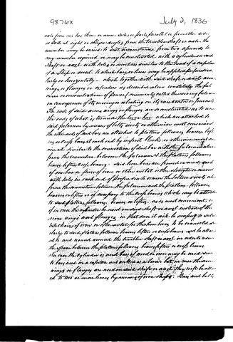
axle from one her three or more sides or parts, parallel or from either side, or both at right or oblique angles from the tumbler shaft or axle. The number may be varied to suit circumstances, from two upwards to any number required, or may be constructed, with a cylinder or said shaft or axle, with holes or notches similar to the head of a capstan of a ship or vessel, to which bars or beams may be applied perpendicularly or horizontally — which together with said shaft or axle, arms, wings, or flanges or extenders as described above constitute the fulcrum or concentration of power (commonly called the moving fulcrum) in consequence of its moving or rotating on its own center or journal.
The ends of said arms, wings or flanges are so constructed as to receive the ends of what is termed the lever bar which are attached to said fulcrum by means of bolts, rivets or otherwise most convenient. The other ends of said bars are attached to platform followers, beams, lifts or roofs beams at each end by iron or blocks or otherwise most convenient, similar to the connection of said bar with the fulcrum above from the connection between the fulcrum and the platform followers, beams, lifts or roofs beams: said lever bars are formed or made of each of one bar or piece of iron or other metal either straight or curved with holes in each end of proper size to receive the bolts or rivets above from the connection between the fulcrum and the platform followers, beams or lifts or of necessary to the roofs beams which may be attached to said platform followers, beams or lifts, as is most convenient, or if in case the cylinder be used on said shaft or axle instead of the arms, wings and flanges in that case it will be necessary to substitute chains of iron or other metal for the lever bars to be connected similarly to said platform followers, beams, lifts or roofs beams and be attached to and wound around the tumbler shaft or axle in order to raise the space between the platform followers, beams, lifts or roofs beams.
In case the cylinder is used bars of wood or iron may be used similar to bars used in a capstan and anchor as above, but in case the arms, wings or flanges are used on said shaft or axle they will be attached to two or more levers by means of iron straps. Bars and bolts
Page 4.
9876x
July 2, 1836
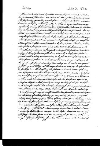
or otherwise to said levers, by which means they are made to act upon the fulcrum (those levers are called the acting levers) in consequence of its performing or acting on the fulcrum the greatest action in pressing or lifting or both jointly together as circumstances may require by means of the connection between the fulcrum by the lever bars or chains being connected with the platen followers, beams, lifters or cross beams, or the end of the humble shaft or axle may be of sufficient length to pass through the part with any inclination as described above, on one end of said shaft or axle instead of the center and be worked by bars above the line or lever when placed perpendicular and attached to the fulcrum will bring the arms wings or flanges to a horizontal position (or a little angling) then by drawing the lever down to a horizontal position by hand with a wheel and windlass or by the action of horse power or steam power or otherwise will cause the arms wings or flanges to change to a perpendicular position acting on its center consequent by pressing and lifting at the same time and reducing the space between the plating etc. The length of the fulcrum at each motion of the lever from a perpendicular to a horizontal position is vice versa said presses and lifters may be constructed of wood and iron or of all iron or other metal and are intended for all the purposes requiring a press or lifter or both jointly in every variety of shapes and forms on the above principle but more particularly for pressing and compression cotton, flax, wool, hay, hops, tobacco, flour, bricks, extracting oils and juices of every description, motion punching and cutting and all kinds of metals, printing in every variety, paper in every state, tanning and finishing, every tools of every description, lifting or raising water by pumps, or otherwise, lifting or raising vessels of every class from and above the water and propelling them through it with velocity—What I claim as my invention is which I deem to seem by Letters Patent consists in the before described mode of applying the lever power and connecting the fulcrum with arms wings or flanges projecting from two, three or more sides or parts of
Page 5.
July 2, 1836
The shaft is used as above described and the mode of using the platform, &c. pressing and lifting at both ends at the same time, simply or lifting separately, for the above named purposes.
Witnesses:
Mr. O'Elliot
Mr. Goulding
Henry G. Guyon
12th and 3
Drawing
Published accounts: journal notice
Notice in the monthly list of patents
Journal of the Franklin Institute, new ser., vol. 18 (1836), p. 359 · View the page
585. Lever press.-G. Guyon, N. Y.
About this record
- Patentee
- Jim Shaw's X-patent list
- Date
- the Name and Date index of patents, USPTO records, Jim Shaw's X-patent list
- Invention
- the Name and Date index of patents
- Listed in
- the Name and Date index of patents, USPTO records, Jim Shaw's X-patent list, the Journal of the Franklin Institute, Burke's List of Patents (1847)
- Burke's 1847 Patent Office list gives the same patent.