

Drawings and documents
USPTO scan
The patent as scanned by the USPTO
-
 Page 1
-
 Page 2
-
 Page 3
-
 Page 4
-
 Page 5


U.S. Patent and Trademark Office · Google Patents
Show the transcription Hide (1,550 words)
Machine transcription (LightOnOCR) of the pages as scanned by the USPTO, most of them the handwritten copies made when the records were restored after the 1836 fire. Not checked; it can misread handwriting, so compare it with the scan.
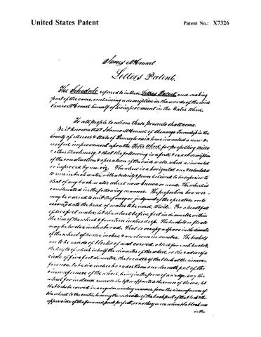
Page 2.
United States Patent
Patent No.: X7326
James W. Bonnet
Letters Patent.
The Schedule referred to in these Letters Patent, once making part of the same, containing a description in the words of the said James W. Bonnet himself of his improvement in the Water Wheel.
To all people to whom these presents shall come.
Be it known that I, James W. Bonnet of Shenango Township in the county of Mercer & State of Pennsylvania have invented a new & useful improvement upon the Water Wheel for propelling Mills & other Machinery, & that the following is a full & exact description of the construction & operation of the said water wheel as invented or improved by me, viz: The wheel is a horizontal one & calculated to run in back water, with a velocity & power believed to be superior to that of any back water wheel now known or used. The wheel is constituted in the following manner. The proportion however, may be varied to suit the fancy or judgment of the operator, or to accommodate the head of water to be used; to wit: For a head fall of two feet water; let the wheel be five feet in diameter, within the rim of the wheel & fourteen inches deep. The buckets or flats may be twelve inches broad. That is occupy a space in the diameter of the wheel of twelve inches, & are eleven in number. The buckets are to be made of blocks of wood curved, a block for each bucket, the length of which is half the diameter of the wheel, or the radius of a circle of five feet diameter, the breadth of the block at the inner circumference, to be six inches broad then one clear with part of the circumference of the wheel, being in the form of a wing, say the wheel for instance runs to the left or opposite to the course of the sun; let the blocks be curved in a regular winding manner, from the inner circumference of the wheel to the center, leaving the under side of the back part of the block & the upper side of the forward part perfect, or as they were when the block was in the
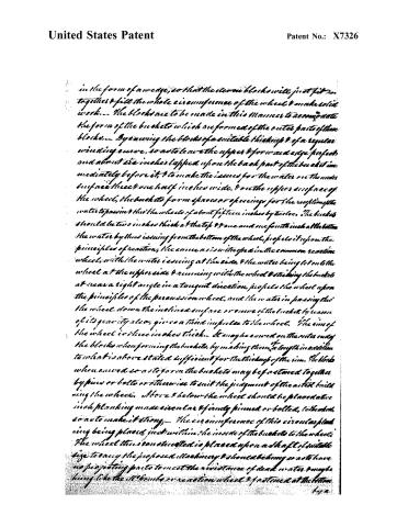
Page 3.
United States Patent
Patent No.: X7326
in the form of a wedge, so that the steam blocks will just fit in, together & fill the whole circumference of the wheel & make solid work. — The blocks are to be made in this manner to accommodate the form of the buckets which are formed of the outer parts of these blocks. — By evening the blocks of a suitable thickness & of a regular winding curve, so as to leave the upper & forward edge perfect and about 2½ inches lapped upon the back part of the bucket immediately before it, & to make the issues for the water on the under surface three & one half inches wide, & on the upper surface of the wheel, the buckets form spaces or openings for the reception of the water to pass in & thru the wheels of about fifteen inches by two feet. The buckets should be two inches thick at the top & one and one fourth inch at the bottom. The water by thus issuing from the bottom of the wheel, propels it upon the principles of reaction; the same as is with the wheel in the common reaction wheel, with the water issuing at the side, & the water being let on the wheel at the upper side & running with the wheel & striking the buckets at near a right angle in a tangent direction, propels the wheel upon the principles of the percussion wheel, and the water in passing thru the wheel, down the inclined surface or curve of the bucket, by reason of its gravity also, gives a third impulse to the wheel. The rim of the wheel is three inches thick. It may be curved on the outer edge the blocks when forming the buckets, by making them, a length in addition to what is above stated sufficient for the thickness of the rim. The blocks when curved so as to form the buckets may be fastened together by pins or bolts or otherwise to suit the judgment of the aforesaid builder using the wheel. Above & below the wheel should be placed two inch planking made circular & firmly pinned or bolted, to the rim, so as to make it strong. — The circumference of this circular planking being placed just within the inside of the buckets to the wheel. The wheel thus constructed is placed upon a shaft of suitable size to carry the proposed machinery & should be hung so as to have no projecting parts to meet the resistance of dead water & maybe hung like the U'bricks or reaction wheel & positioned at the bottom.
142
Page 4.
United States Patent
Patent No.: X7326
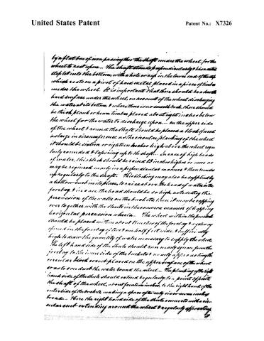
by a flat bar of iron passing through the shaft under the wheel, for the wheel to rest upon. The shaft stands perpendicularly & has a metal step let into the bottom, with a hole or eye in the lower end of the step which rests on a pivot of hard metal placed in a piece of timber under the wheel. It is important that there should be a smooth hard surface under the wheel, on account of the wheel discharging the water at its bottom, & where there is no smooth rock, there should be thick plank or hewn timber placed about eight inches below the wheel for the water to discharge upon. On the upper side of the wheel & round the shaft should be placed a block of wood as large in circumference as the circular planking of the wheel it should be sixteen or eighteen inches high above the wheel regularly rounded & tapering up to the shaft. In case of high heads of water, this block should be raised 12 inches higher or more as may be required nearly in a perpendicular manner & then rounds up regularly to the shaft. This blocking may also be supplied by a hollow curb in its place, to raise above the head of water in the forbay, & in case the head should be so high, as to destroy the percussion of the water on the buckets, then it may be capped over together with the chute in the common manner of capping horizontal percussion wheels. The wheel within the penstock should be placed within about 15 inches of the forbay & a gateway opened in the forbay of two & one half feet wide, & sufficiently high to draw the quantity of water necessary to supply the wheel. The left hand side of the chute should run nearly square from the forbay to the inner side of the buckets & nearly a foot a side length the circular block or curb placed on the upper surface of the wheel so as to encroach the water round the wheel. The planking of the right hand side of the chute should extend regularly to a point opposite the shaft of the wheel, about fourteen inches, to the right hand of the outside of the buckets, making a space of twenty six or seven inches broad. Where the right hand side of the chute connects with a circular curb extending around the wheel & regularly approaching
Page 5.
United States Patent
Patent No.: X7326
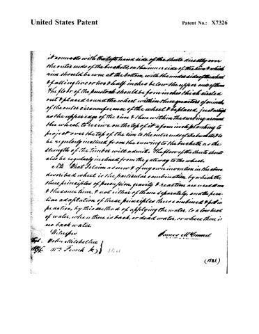
it comes to with the left hand side of the chute directly over
the outer ends of the buckets, on the inner side of the rim, which
rim should be worn at the bottom, with the under side of the wheel
& falling two or two & half inches below the upper end of them
The floor of the pumice should be four inches thick, circled
out & placed round the wheel within three quarters of an inch,
of the outer circumference of the wheel & be placed, just as high
as the upper edge of the rim & then within the curving around
the wheel, to receive on the top of it a four inch planking to
project over the top of the rim to the outer ends of the buckets, to
be regularly inclined from the curving to the buckets, as the
strength of the timber will admit. The floor of the chute should
also be regularly inclined from the gateway to the wheel.
e.t.b. What I claim as new & of my own invention in the above
described wheel is the particular combination, by which the
three principles of percussion, gravity & reaction are used at one
& the same time, & not either of them separately, and the peculiar
adaptation of these principles thus combined & put in
practice, by this method of applying the water, to a low head
of water, when there is back, or dead water, or where there is
no back water.
Witnesses
James Ell Comnel
Capt. John Mitchell
Wm. Frank Jr.
(1821.)
Published accounts: journal notice
Notice in the monthly list of patents, with remarks
Journal of the Franklin Institute, new ser., vol. 11 (1833), p. 377 · View the page
1 This thrashing machine is to be used not only for thrashing grain, but also for grinding (or hackling) apples. There are to be bars and spikes on a cylinder, and bars and spikes on a concave, and the improvement claimed is "the bars and spikes of the cylinder acting upon the grain over the concave of bars, and over and between the spikes in the concave at the same time; and also the application of the machine to grinding apples.” 16. For an improvement in the Water Wheel; James M'Connel, Shenango, Mercer county, Pennsylvania, December 13.
Remarks. The patentee claims, in the action of his wheel, the conjoint operation of three powers, all derived from the descent of the water; it is to be a horizontal, reaction wheel, receiving the water on its upper, and discharging it on its lower side. There are to be eleven buckets, extending from the periphery of the wheel towards its centre, about one-half the semidiameter; the buckets are to be curved from the top to the bottom in such a way as to deliver the water advantageously in its exit. The wheel is, of course, to run in a penstock, with a Vo. XI. No. 6.-JUNE, 1833. 48 suitable curbing, to direct the water. The buckets overlap about six inches, at their outer ends, that is, a line drawn perpendicularly from the lower edge of one bucket, would cut off about six inches of the contiguous bucket. Not only the number of the floats or buckets, but the precise dimensions of every part, are given; a detail into which it is not necessary for us to enter. We are told that this wheel will run in back water with more facility than any other, and that it is particularly adapted to places where the head is low, and the wheel liable to be flooded. The three powers which act upon it are thus set forth by the patentee; he says that the water issuing from the bottom of the wheel propels it upon the principle of reaction; that the water being let on at the upper side, and running with the wheel, and striking the buckets nearly at right angles, propels it upon the principle of percussion; and that the water in passing down through the wheel, acting on the inclined surface of the buckets, gives a third impulse on the principle of gravity. The claim is to the practical combination of these three principles of percussion, gravity, and reaction, used at one and the same time. We are unable to trace the particular and special coadjutorship of these three principles in this wheel, and could as readily ascribe them to several others; we are, however, so much inclined to resolve all these modes of action into gravity, and to view them as merely different methods of applying this property of matter, as not to acknowledge the employment of any other power in the propelling of water wheels. Reaction and percussion we esteem as the children of gravitation, and would never commend their employment when the fall of water is sufficient in height to enable the millwright to fill the buckets of an overshot, or pitch-back wheel; that is, when it is necessary to husband power.
About this record
- Patentee
- DATAMP
- Date
- the Name and Date index of patents, DATAMP, USPTO records
- Invention
- DATAMP
- Listed in
- the Name and Date index of patents, DATAMP, USPTO records, Jim Shaw's X-patent list, the Journal of the Franklin Institute, Burke's List of Patents (1847)
- Burke's 1847 Patent Office list gives the same patent.