

Drawings and documents
USPTO scan
The patent as scanned by the USPTO
-
 Page 1
-
 Page 2
-
 Page 3
-
 Page 4
-
 Page 5


U.S. Patent and Trademark Office · Google Patents
Show the transcription Hide (1,711 words)
Machine transcription (LightOnOCR) of the pages as scanned by the USPTO, most of them the handwritten copies made when the records were restored after the 1836 fire. Not checked; it can misread handwriting, so compare it with the scan.
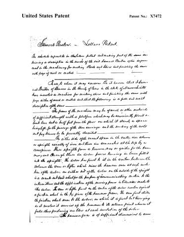
Page 2.
United States Patent
Patent No.: X7472
Samuel Preston. — Letters Patent.
The schedule referred to in the letters patent and making part of the same contains a description in the words of the said Samuel Preston of his improvement in the machinery for making Boots and Shoes and finishing the same with pegs of wood or metal.
To all to whom it may concern. Be it known that I, Samuel Preston of Hanover in the County of Essex in the State of Massachusetts have invented a machine for making shoes and finishing the same with pegs, either of wood or metal and that the following is a full and exact description of the same.
The frame of the machine may be of wood or other material of sufficient strength with a platform which may be conveniently placed about two and a half feet from the floor on which it stands, a space being left for the passage of the shoe carriage and the working of the wheels and peg drivers to be presently described.
On either side of the vacant space in the center rise columns or uprights, usually of iron and these are connected at the top by a crosspiece. These uprights form a traverse way or guide for the hammer, and through these an arbor passes, turning in boxes fitted into the uprights. The arbor has fixed to it in the centre between the columns the cam or lifter which raises the hammer once at each revolution of the arbor; on either end of the arbor on the outside of the upright is a crank and band wheel for the purpose of communicating motion to the intermitter and the application of the moving power is likewise made to this arbor. The cam or lifter fixed on the centre of the arbor revolves against a friction wheel in the top piece of the hammer frame. The cam first strikes the friction wheel near to the arbor, on which it is fixed but diverging as it revolves it carries up the hammer to its extreme point whence it falls, thus producing one blow at each revolution of the arbor.
The hammer face is of sufficient dimensions to cover
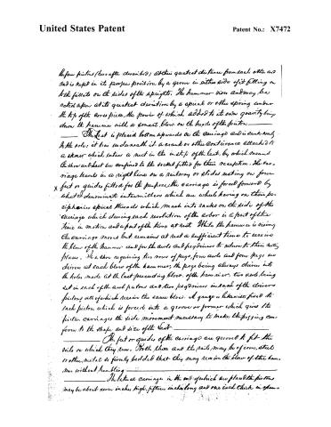
Page 3.
United States Patent
Patent No.: X7472
The four pistons (hereafter described) at their greatest distance from each other are and is kept in its proper position by a groove in either side of it fitting on to the facets on the sides of the uprights. The hammer rises and may be acted upon at its greatest elevation by a spiral or other spring under the top of the cross piece, the power of which added to its own gravity brings down the hammer with a smart blow on the heads of the pistons.
The last is placed bottom upwards on the carriage and is sunk nearly to the pole; it has underneath it a crank or other contrivance attached to a screw which enters a nut in the inside of the last, by which means the shoe and last are confined to the socket fitted for their reception. The carriage travels in a right line on a railway or slides resting on four feet or guides fitted for the purpose. The carriage is forced forward by what I denominate intermitters which are wheels having on their peripheries spiral threads which mesh into racks on the side of the carriage which during each revolution of the arbor is a part of the time in motion and a part of the time at rest. While the hammer is rising the carriage moves but remains at rest a sufficient time to receive the blow of the hammer and for the awls and peg drivers to return to their resting places. In a shoe requiring two rows of pegs, four awls and four pegs are driven at each blow of the hammer, the pegs being always driven into the holes made at the last preceding blow of the hammer, two awls being set in each of the awl pistons and two peg drivers in each of the drivers pistons, all of which receive the same blow. A gauge is likewise fixed to each piston which is forced into a groove or former which gives to the piston carriage the side movement necessary to make the pegging conform to the shape and size of the last.
The feet or guides of the carriage are grooved to fit the rails on which they run. Both these and the rails may be of iron, steel or other metal so firmly bedded that they may receive the blow of the hammer without trembling.
The lateral carriage in the end of which are placed the pistons may be about seven inches high, fifteen inches long and one inch thick in plan.
Page 4.
United States Patent
Patent No.: X7472
and intermitters occupy their assigned stations; that is at each succeeding blow the peg driver occupies the exact station which the awl occupied at the blow preceding it and consequently cannot fail of depositing the peg which it starts in the hole made by the awl which was its leader.
The racks on the sides of the shoe carriage have teeth of that degree of fineness which is necessary for the kind of work to be performed. The teeth being set, at the same distance from each other as is intended for the pegs on the shoe. The intermitter being so made as to mesh into them.
The intermitters being cut with a gain equal to a two threaded screw, on one half of its periphery and on a line with the motion of the wheel on the other half, or the threads may be entirely omitted on the other half; as the carriage whilst the wheel is passing over the space without a thread will necessarily remain at rest. The specially threaded part, will take each succeeding tooth of the rack in its turn in the same manner as if the thread were continued on that space in a right line with the movement of the wheel, or if a gain equal to a three threaded screw be cut, the carriage will be left at rest two thirds of the time. The operation of the intermitters on the shoe carriage is to give it motion at intervals. By the straight thread or the vacant space on the intermitters the shoe carriage is left at rest, a sufficient time during each revolution for the pistons to receive the blow of the hammer and for them to return to their resting places before the moving power exerts its influence again. Bands and rods with band wheels and cranks connected or cog wheels in their stead serve to communicate motion in equal revolutions from the awl to the intermitters.
The cases in which the slips of pegwood properly fitted lie, may be firmly fixed at an angle of about 45° to the carriage of the peg driver pistons with one end directly under the pistons and the peg drivers themselves moving in the ends of the cases. The slips of pegwood are put into the cases by hand and are forced against the end when the peg driver slides up and down by means of a straight, and pulley, attached to a follower. In the end of the case where the peg driver plugs at the distance of the width of one peg from the bottom of the case is an edge or splitter about one eighth of an inch.
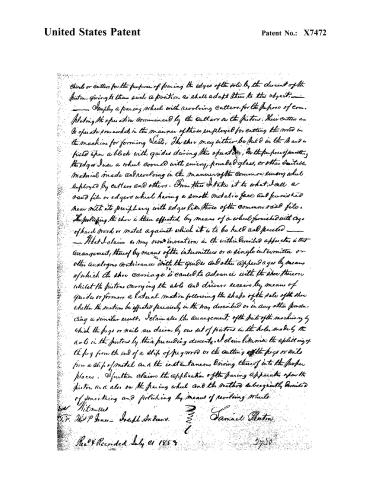
Page 5.
United States Patent
Patent No.: X7472
chisel or cutters for the purpose of paring the edges of the sole by the descent of the pistons, giving to them such a position as shall adapt them to this object.
— Employ a paring wheel with revolving cutters for the purpose of completing the operation commenced by the cutters on the pistons. These cutters are to operate somewhat in the manner of those employed for cutting the wood in the machine for forming Vests. The shoe may either be held in the hand or fixed upon a block with guides during this operation, for the purpose of smoothing the edges. Use a wheel covered with emery, pounded glass, or other suitable material made and revolving in the manner of the common emery wheel employed by cutters and others. From this I take it to what I call a sand file or edgers wheel having a smooth metallic face and furnished near with its periphery with edges like those of the common sand file. The polishing the shoe is then effected by means of a wheel furnished with a row of hard wood or metal against which it is to be held and pressed.
— That I claim as my own invention in the within described apparatus is that arrangement, thereof by means of the intermitter or a single intermitter or other analogous contrivance with the guides and other appendages by means of which the shoe carriage is caused to advance with the shoe thereon whilst the pistons carrying the abls and drivers receive by means of guides or formers a lateral motion following the shape of the sole of the shoe whether the motion be effected precisely in the way described or in any other producing a similar result. I claim also the arrangement of the parts of the machinery by which the pegs or nails are driven by one set of pistons in the holes made by the nails in the pistons by their preceding descent. I claim likewise the splitting of the peg from the end of a slip of pig iron or the cutting off the pegs or nails from a slip of metal and the instantaneous driving thereof into the proper places. I further claim the application of the paring apparatus upon the pistons and also on the paring wheel and the method subsequently described of smoothing and polishing by means of revolving wheels.
Witnesses
W. P. Jones — Joseph Andrews.
Samuel Panton
Rec’d & Recorded July 21 1854.
2730
Published accounts: journal notice
Notice in the monthly list of patents, with remarks
Journal of the Franklin Institute, new ser., vol. 12 (1833), p. 173 · View the page
15. For Machinery for Making and Pegging Shoes; Saml. Preston, Danviers, Essex county, Massachusetts, March 8.
Remarks. This is an ingeniously contrived, and, we think, a well arranged apparatus for making shoes, fastened by wooden or metallic pegs. The specification is of considerable length, and although it describes the machine clearly, it would require an engraved plate for its illustration. The claims made are the following:"What I claim as my own invention in the within described apparatus, is that arrangement thereof by means of the intermitters, or a single intermitter, or other analogous contrivance, with the guides, and other appendages, by means of which the shoe carriage is caused to advance with the shoe thereon, whilst the pistons carrying the awls and drivers, receive, by means of guides, or formers, a lateral motion, following the shape of the sole of the shoe; whether these motions be effected precisely in the way described, or in any other producing a similar effect. " I claim also the arrangement of the parts of the machinery by which the pegs, or nails, are driven by one set of pistons, in the holes made by the awls in the pistons by their previous descent. "I claim, likewise, the splitting the peg from the end of a slip of pegwood, or the cutting of pegs or nails, from a strip of metal, and the instantaneous driving thereof into the proper place. "I further claim the application of the forcing apparatus, the piston, and also the forcing wheel, and the method, subsequently described, of smoothing and polishing by means of revolving wheels."
About this record
- Patentee
- DATAMP
- Date
- the Name and Date index of patents, DATAMP, USPTO records
- Invention
- DATAMP
- Listed in
- the Name and Date index of patents, DATAMP, USPTO records, Jim Shaw's X-patent list, the Journal of the Franklin Institute, Burke's List of Patents (1847)
- Burke's 1847 Patent Office list gives the same patent.