

Drawings and documents
USPTO scan
The patent as scanned by the USPTO
-
 Page 1
-
 Page 2
-
 Page 3
-
 Page 4
-
 Page 5
-
 Page 6
-
 Page 7
-
 Page 8


U.S. Patent and Trademark Office · Google Patents
Show the transcription Hide (2,483 words)
Machine transcription (LightOnOCR) of the pages as scanned by the USPTO, most of them the handwritten copies made when the records were restored after the 1836 fire. Not checked; it can misread handwriting, so compare it with the scan.
Page 1.
No Printed Specification Available.
7915½X
S. H. Long,
Steam Slide Valve.
Patented Dec. 30, 1833.
Fig. 10.
Fig. 7.
Fig. 9.
Fig. 6.
Fig. 8.
Fig. 5.
Fig. 2.
Fig. 3.
Fig. 1.
Fig. 4.
K. PETERS, PHOTO-LITHOGRAPHER, WASHINGTON, D. C.
Page 2.
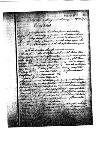
Stephen A. Long. U. S. Army 79155X
Letters Patent
The whole subject to in their Letters Patent and making part of the same containing a description in the words of the said Stephen A. Long himself of his improvement in the construction of various Steam Valves, of Locomotive and other Steam engines, the Force Pumps of such engines and the whole for Locomotive engines.
To all to whom these presents shall come
Be it known that S. Stephen A. Long of the United States Army have invented and applied certain new and useful improvements in the construction of the main Steam valves of the various Locomotive and other Steam engines. Also in the construction of the force pumps of such engines. And also in the manner of constructing the whole of Locomotive Engines and of other Railway Carriages and that the following is a full and exact description of my said improvements.
First of the main Steam valve:
My improvement in the steam valve consists in the adoption of two slide valves one above the other, which I designate the upper and lower slide valves, and which in conjunction I denominate the double slide valve. The object of the upper valve is to introduce a part of the passage of the steam into the cylinder at about half of any stroke of the piston while that of the lower valve is to regulate the admission of steam after entering into each end of the cylinder.
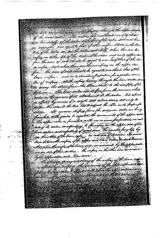
The lower valve differs from the ordinary slide valve in having its upper surface concave at both ends in the direction of the movement far enough to give place to the edges and the periphery of the lower valve and also so that a portion of the steam passing through the valve is not cut off by the edge of the
Page 3.
into her, or merely acting as a stay, owing things to the upper surface of the common valve. The valves last mentioned are of equal area but inversely of the valve with that of the valve seat and have an aggregate sum equal to that of either surface situated in the lower side of the valve or in the valve seat itself, when there are two valves on either side of the center of the valve and only upper and lower the area of each should be equal to one-half that of the lower surface, and when there are three valves in the upper surface, the area of each should be equal to one-third that of the lower surface, and in a similar proportion for a greater number of valves. All the valves leading through the lower valve seat to carry the steam from the steam chest to the orifices of the cylinder. The lower valve also differs from the common slide valve in the manner of its attachment to the valve rod which is effected by means of a single nut which serves not only to confine the valve to the rod but to adjust the valve in its proper position. It moreover differs from the common valve in being furnished with guides to regulate the movements of the upper valve. The upper valve is furnished with one or more perforations on each side of its center corresponding to the orifices on the upper side of the lower valve, and respectively of equal area. The number being less by one than that of the lower valve, on each side of its center. The connection between the orifices of the upper and lower valves is such however that when the orifices of the lower valve are uncovered by the upper valve on one side of their centers, the orifices on the other side are covered by the upper valve and vice versa.
The attention, opening and closing of the orifices of the lower valve is effected by interrupting the movement of the upper valve and consequently the lower valve to the extent which the upper valve moves upward. The valve between the upper and lower valves is so arranged that the orifices of the lower valve are exposed to the action of the steam when the upper valve is moving upward, and the orifices of the lower valve are covered when the upper valve is moving downward.
Page 4.
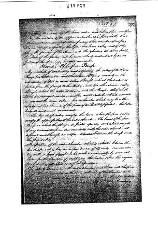
The dimensions of the lower valve and when there are three valves, the motion of the upper valve should be inversely to that of the lower and in due proportion for any other number of valves. The manner of adjusting the upper and lower valves and of introducing the passage of the steam into the cylinders at about half the depth of the piston will be more clearly understood by an inspection of the drawings here to be annexed.
Second. Of the force Pump.
My method of constructing and adjusting the valves of the Force Pump for Locomotive and the Steam Engine consists in the introduction of two or more valves through which the water is forced from the pump to the Boiler, and two other similar valves through which the water is drawn into the Pump, all of which valves are arranged one above another and at suitable intervals, one under the other and the same valve-box or chamber which may be either of a cylindrical form or of the form of a Parallel-sided. The latter being deemed most convenient.
The two draft valves occupy the lower while the force valves occupy the upper portion of the valve chamber. The barrel of the force Pump in which the plunger or piston operates and which may be of any convenient form communicates with the valve chamber at a point and through an orifice situated between the draft and the force valves.
The portion of the valve chamber which is situated between the two draft valves has an orifice in one of its sides communicating with a hand pump to be worked occasionally by manual labor for the purpose of supplying the boiler when the engine to which it is attached is not in operation.
The water drawn into the valve chamber and thence into the force pump through an orifice in the lower extremity of the chamber and again from the same through a similar orifice in the upper portion of the chamber. Each extremity of the valve chamber is provided with a bottom valve by which it is effectively closed.
Page 5.
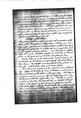
in a manner to prevent all leakage — The entire front of the valve chamber except a small moulding at the top and bottom is crossed by three lines either or all of which may be removed and replaced at pleasure by means of the screw bolts which confine them to the chamber — The form of the chamber may be cylindrical or square as may be found most convenient. The square form is however deemed preferable inasmuch as it affords greater facility for the insertion of the valves and for the adjustment of the bars or levers.
Third of the Wheels
In addition to former improvements in the construction of the wheels of the Pennsylvania locomotive, I claim as a new and useful improvement in the construction of locomotive engines, the application of circular iron hubs cast in a single piece each for the reception of wooden spokes, said hubs being constructed after the manner heretofore adopted by W. Stinley of Philadelphia in the construction of business and passenger cars.
I also claim as a new and useful improvement in the construction of car wheels and especially of the wheels of locomotive engines, the adoption and use of double fittings of wood in connection with cast iron hubs and wooden spokes.
The wheel rim is composed of two distinct series of half-felt legs applied to the spokes by means of notches in each series embracing the tenons of the spokes instead of mortises. The fittings are arranged in such a manner that the half-fittings of one series break joints with those of the other series. By this means the necessity of dovelling the fittings together is obviated although dovelling in this square or round may be employed if desirable. The double fittings are firmly bonded together by nails passing through them near to and on both sides of every spoke. In applying the nails to the wheel rim, the construction of the same should be taken to avoid driving the nails nearly half into the grooves of the fittings. A method to connect the fittings more firmly together
Page 6.
7915½X 319.
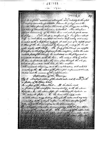
need to impart additional strength and solidity to the sheet I employ iron clamps situated between the felloes and the tire at those points where the ends of the felloes are united and when of course the tension is greatest. These clamps are applied transversely of the wheel rim and extend quite across the felloes. Each clamp is composed of a bar of iron about half an inch thick and about one and a half inches wide and is furnished with a half head or joggle at each end of a depth equal to that of the bar and formed by bending the ends of the bar at right angles with itself. The heads of the clamps are adapted to recesses in the felloes prepared for their reception while the intermediate parts of the clamps lie imbedded in the felloes and in immediate contact with the tire. The nails or bolts by which the tire is fastened upon the rim pass through the clamps which are furnished with holes for their reception.
The annexed drawings and their explanation will exhibit more clearly the nature of the principal improvement above described and the manner of their application.
Explanation of the Drawings
Fig 1. A vertical section of the double valve and its seat, with a portion of the Steam Chest.
A a part of the Steam Chest — B the valve seat — a portions of the side pipes communicating with the steam cylinder — b the steam pipe for exhausting the cylinder or the exhaust pipe — C the lower slide side valve — c the steam ways leading through the valve each way communicating with a single orifice in the lower surface of the valve and with three orifices in its upper surface — D the upper slide valve communicating with the lower valve by means of the orifices d, d. The movement of the upper valve is effected by sliding on the upper surface of the lower valve and in such a manner as to allow the steam ways through the latter alternately to communicate with the orifices
Page 7.
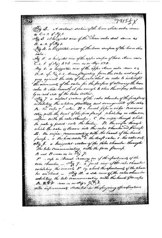
Fig. 2. A vertical section of the lower slide valve same as C. c. 2 of Fig 1.
Fig 3. A horizontal view of the Steam valve seat same as B. a. 2. of Fig 1.
Fig 4. A horizontal view of the lower surface of the lower slide valve.
Fig 5. A horizontal view of the upper surface of lower steam valve. C. c. 6 of Fig 1 & 3 same as in Fig 1. 92.
Fig 6. A horizontal view of the upper steam valve same as D. a. of Fig 1. c. Arms projecting from the valve and impinging against the sides of the valve chest in order to intercept the movements of the valve for the purpose of allowing the lower valve to slide beneath it far enough to close the orifices alternately in each side of the valve chest.
Fig 7. A vertical section of the valve chamber of the force pump exhibiting the relative positions and arrangement of the valve. A. the valve & inlet. B a branch pipe or orifice communicating with the barrel of the force pump which has no other connection with the valve chamber. C. the orifice through which the water is forced into the boiler. D. the orifice through which the water is drawn into the valve chamber and pump. E. the orifice communicating with the barrel of the hand pump. a the force valve b the draft valve. c. the valve seat.
Fig 8. A horizontal section of the valve chamber through the tube communicating with the force pump. A and B same as in Fig 7.
F. a valve or Bonnet covering one of the apartments of the valve chamber — Fig 9. A front view of the valve chamber exhibiting the bonnet F by which the apartments of the chamber are closed — Fig 10. A side view of the valve chamber exhibiting the tube communicating with the hand pump. A. E & F same as in Fig 7 & 8.
The improvements described in the foregoing specifications.
Page 8.
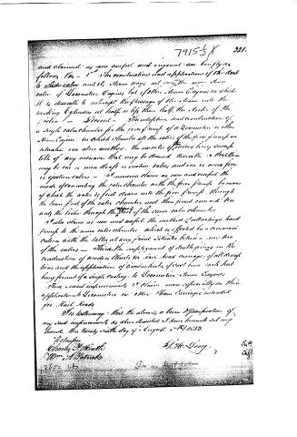
and claimed as new, useful, and original are briefly as follows. First — 1st — The construction and application of the double slide valve and its steam ways, not only the main steam valve of locomotive Engines, but of other Steam Engines in which it is desirable to intercept the passage of the steam into the working cylinder at half or less than half the stroke of the piston — Second — The adoption and construction of a single valve chamber for the force pump of a locomotive or other Steam Engine in which chamber all the valves of the force pump are situated one above another, the number of valves being subject to little of any increase that may be deemed desirable so that there may be one or more draft or suction valves, and one or more force or ejection valves — I moreover claim as new and useful the mode of connecting the valve chamber with the force pump by means of which the water is first drawn into the force pump, through the lower part of the valve chamber and then forced once and twice only the water through the upper part of the same valve chamber. I also claim as new and useful the method of attaching a hand pump to the main valve chamber which is effected by a communication with the latter at any point situated between any two of the valves — Third — The employment of double joints in the construction of wooden wheels for rail road carriages, of all descriptions and the application of circular hubs of cast iron each hub being formed of a single casting, to locomotive steam Engines. These several improvements I claim more especially in their application to locomotive or other Steam Carriages intended for Rail Roads.
In testimony that the above is a true Specification of my said improvements as above described I have hereunto set my hand this twenty sixth day of August 1833.
Witnesses
Charles F. Kershaw
Wm. A. Paterno
J. H. Long
2652 1833
Pat. & Dep.
Published accounts: journal notice
Notice in the monthly list of patents, with remarks
Journal of the Franklin Institute, new ser., vol. 14 (1834), p. 26 · View the page
65. For Steam Valves, Force Pumps, and Wheels for Locomotive Engines; Stephen H. Long, Colonel in the United States Army, and attached to the corps of Civil Engineers; city of Philadelphia, December 30.
Remarks. The claims under this patent are to the construction and application of a double slide valve, for the purpose of interrupting the passage of the steam into the cylinders at half, or less than half, stroke. The adaptation and construction of a single valve chamber for the force pump, in which all the valves are situated one above another, there being any number of them which may be deemed desirable, as one, or more, suction, and one, or more, ejection, valves. The mode of connecting the valve chamber with the force pump, so that the water is first drawn into the pump through the valve chamber, and forced out towards the boilers, through the upper part of the same. The mode of attaching a hand pump to the valve chamber. The employment of double felloes for the wooden wheels of rail-road carriages, and the application thereto of circular hubs of cast iron, formed of one single casting. The double valve consists of two separate slides, one of which is, like the ordinary slide valve, to admit the steam alternately into each end of the cylinder, the other is to cut off the passage of the steam into the steam cylinder at about half of every stroke of the piston. Without the drawings it would be extremely difficult to describe the particular mode of constructing and regulating the steam ways of these valves, as adopted by the patentee, and we do not think it necessary to make the attempt. The same remark will apply to the force pumps. As regards the cast iron hubs, we are told that the improvement consists in the application to locomotive engines, of such iron hubs as R. Imlay, of Philadelphia, has applied to burthen and passage cars. This, we apprehend, is a claim which has no foundation whatever upon which to establish a patent. The taking a wheel, or a part of a wheel, invented by another person, and applying it to a carriage of another kind, is, certainly, not an invention or discovery. Mr. Imlay has not thought proper to take a patent for the hub in question, nor are we aware that there is enough of novelty in it to sustain one, but however this may be, the contrivance cannot be claimed by another. The double felloes which compose the rim of the wheel, are to lap over each other so as to break joints, each being halved out at every spoke, so as, when put together, to form a mortise. The felloes are to be united by iron rivets passing through them, near to the joints; and before hooping, they are to be further secured by clamps of iron which cross them transversely, having a jog, or half head, turned down at each end to embrace the felloes. Over these is put the iron tire, and the bolts securing it on pass through holes prepared in them for that purpose. We do not perceive in this arrangement any thing which is likely to obviate the difficulty experienced in keeping wood and iron tight together in locomotive engines and cars. The expansion and contraction of the wood from moisture and dryness; the oxidation of the iron, and the sure effect of continued vibration, have hitherto destroyed junctures which were apparently so firm that no ordinary force could affect them; we shall be glad to learn that such is not the case with those made upon the plan here proposed.
Published accounts: journal notice
Notice in the monthly list of patents, with remarks
Journal of the Franklin Institute, new ser., vol. 14 (1834), p. 112 · View the page
9. For A Vice; James Long, Harrison county, Virginia, January 10.
Remarks. This is a wooden vice, denominated by the patentee the "Superior Vice," and since there is no standard given by which to judge, and there are undoubtedly some which are inferior to it, the name need not be objected to. It is to be tightened by a wedge, and is to be used by wheelwrights, coach-makers, joiners, &c., instead of that usually tightened by a screw. Like other wooden vices, it has two upright jaws, one of which is to be made fast to the bench, whilst the other works upon a joint at its lower end; this, which is the front jaw, has a mortise through it at the part usually appropriated to the screw; and a long tenon, which is firmly attached to the back jaw, passes loosely through this mortise, and receives wedges which tighten the jaw, or cheek. When the wedge is to be removed the jaw is opened by placing the foot upon a treadle at its lower end, which, when pressed down, bears against a friction roller in the back jaw. A spring is so fixed as to close it when the foot is taken off the treadle. We are told that by facing the inside of the jaws with steel, this will be found to be a very cheap and useful vice for a blacksmith; there are, however, but few blacksmiths, we believe, who would be willing to use it, if they could procure one of iron. The patentee sets forth the good qualities of his invention very much at large, but as its construction will be easily understood, we leave it to tell its own tale.
About this record
- Patentee
- Jim Shaw's X-patent list
- Date
- the Name and Date index of patents, USPTO records
- Invention
- the Name and Date index of patents
- Listed in
- the Name and Date index of patents, USPTO records, Jim Shaw's X-patent list, the Journal of the Franklin Institute, Burke's List of Patents (1847)
- The sources give different dates; the date shown is the one most of them agree on.
- The Franklin Institute's journal confirms the date shown.
- Burke's 1847 Patent Office list gives the same patent.
- Burke's 1847 Patent Office list gives a slightly different date; the date shown follows the standard lists.
- Residence from Burke's 1847 Patent Office list; the standard lists give none.