

Drawings and documents
National Archives restored drawings: drawing
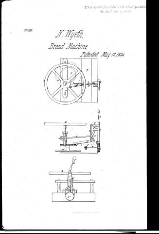
N. Wyeth's Patent Drawing for a Bread Machine

National Archives, Restored Patent Drawings (Record Group 241) · Full-size scan at the National Archives · Catalog record
Show the text on the drawing Hide (28 words)
Words on the drawing as machine-read by the National Archives; not checked. Useful mainly for searching.
N Wijeth, / Bread Machine, / Xbs18 / Patented May 12,1834 / -7- / L° / K.W.
USPTO scan
The patent as scanned by the USPTO
-
 Page 1
-
 Page 2
-
 Page 3
-
 Page 4


U.S. Patent and Trademark Office · Google Patents
Show the transcription Hide (1,122 words)
Machine transcription (LightOnOCR) of the pages as scanned by the USPTO, most of them the handwritten copies made when the records were restored after the 1836 fire. Not checked; it can misread handwriting, so compare it with the scan.
Page 1.
8189X
N. Wyeth,
Bread Machine,
Patented May 12, 1834
The specification in this patent is not in print.
Page 2.
5/12/1834 8189 X
May 12, 1834
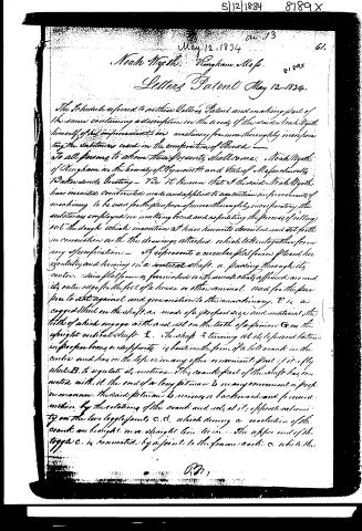
Noah Myths. Wingham. Mass. 8189X
Letters Patent May 12, 1834.
The Schedule referred to in this Letters Patent and making part of the same containing a description in the words of the said Noah Myths himself of his improvements in machinery for more thoroughly incorporating the substances used in the composition of Bread.
To all persons to whom these presents shall come, Noah Myths of Wingham in the County of Plymouth and State of Massachusetts, Greeting.
Be it known that the said Noah Myths have invented, constructed, made and applied to use certain improvements of machinery to be used for the purpose of more thoroughly incorporating the substances employed in making bread and expediting the process of rolling out the dough which invention I have hereunto described and set forth in connection with the drawings attached which taken together form my specification.
A represents a circular platform placed horizontally and turning on a vertical shaft. a. passing through its centre. Said platform is furnished with small chairs affixed around its outer edge for the feet of a horse or other animal used for the purpose to act against and give motion to the machinery. E is a cogged wheel on the shaft, as made of a proper size and material, the teeth of which engage with and act on the teeth of a pinion G on the upright vertical shaft E. The shaft E turning at its lower end in a proper box or supports is bent in the form of a bell crank in the centre and has on the top or in any other convenient part of it, a fly wheel B to regulate its motions. This crank part of the shaft has connected with it the end of a long pitman D in any convenient or proper manner. The said pitman D receives a backward and forward motion by the rotation of the crank and acts at its opposite extremity on the two toggle joints C, C, which during a revolution of the crank are brought more straight than usual. The upper end of the toggle C is connected by a joint to the frame work C, while the
Page 3.
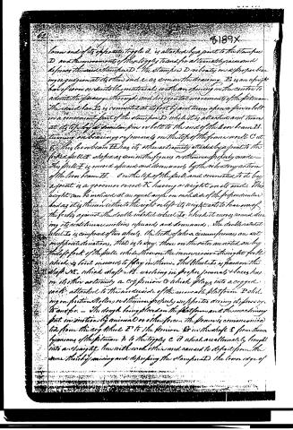
lower end of its opposite toggle d. is attached by a joint to the stamp D and the movements of these toggles to and fro alternately raise and depress the said stamp D. The stamp D vibrates in a proper bar in or against at its other end e, as seen in the drawing. D is an upright bar of iron or suitable material with an opening in the center to admit the passage through and horizontal movements of the piston. The said bar D is connected at its foot by and turns upon a pin or bolt in a convenient part of the stamp D, while it is attached and turns at its top by a similar pin or bolt to the end of the lever beam H, turning on bearings or journals on the top of the frame work C at S. This lever beam H has its other extremity attached by a joint to the forked pull E as shown as seen in the figures or otherwise properly made. The pull E is moved upwards and downwards by the vibratory action of the lever beam H. On the top of the pull and connected to it by a joint is a governor rod K having a weight on its end. This weight can be inclined at an equal angle on each side of the perpendicular and as it is thrown either to the right or left its weight acts to bear one of the forks against the double ratchet wheel T, which it moves round during its rectilinear motions upwards and downwards. The double ratchet wheel T is composed of two wheels, the teeth of whose circumferences are set in opposite directions, that is to say, those on the outer are acted on by the left fork of the pull, while those on the inner receive the right fork, which is kept in order to play in them. The wheel T is fixed on the shaft N, which shaft N, working in proper journals & boxes has on its other extremity a cog pinion O which plays into a cogged rack attached to the under side of the movable platform P sliding on friction rollers, and the same properly supported during its passage to and fro. The dough being placed on the platform and the machinery put in motion by animal or other force, the force is communicated to from the cog wheel E to the pinion O in the shaft S from the bearings of the piston B to the toggles C & d which are alternately brought into and say at the with each other and caused to depress from the same thereby moving and depressing the stamp D the lower edge of
Page 4.
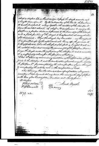
which is shaped like a blunt wedge to press the dough asunder as it is brought down upon it. By the intervention of the bar E, the lever beam H and forked pulley acting together the motion of the stamp D turns the catshot wheels, its shaft M and pinion O moving the platform a proper distance to present to the lower edge of the stamp D a fresh portion of the dough to be expatiated at every stroke of it consecutively. When the dough has been acted on throughout it is doubled up by the attendant who throws off the griddle K to the opposite side when the other fork of the pull is brought to act in the catshot wheel and across the movement of the platform P and brings the dough under the influence of the stamp D and so on until it is sufficiently rolled for the purpose of baking.
What I claim as new and my invention is the application of toggle joints to the stamp D and the combination of machinery for moving the platform P for accomplishing the above purpose of more thoroughly incorporating the articles used in the composition of bread.
In testimony that the above is a true specification of my said invention I have hereunto set my hand this nineteenth day of April in the Year of our Lord eighteen hundred and thirty-four.
Witnesses
Robert McCarty
W.E. Quinault
Noah Myatt.
Drawing
1079 no
8184X
69.
Published accounts: journal notice
Notice in the monthly list of patents, with remarks
Journal of the Franklin Institute, new ser., vol. 14 (1834), p. 392 · View the page
9. For a machine for Kneading Dough for Making Bread; Noah Wyeth, Hingham, Plymouth county, New Hampshire, May 12.
Remarks. The dough is to be placed upon a movable platform, which is made to traverse backward and forward by means of a double rack and pinions operating beneath it. A stamper working upon a pin at one end, and being raised and depressed at the other by the action of a toggle joint, works up and down upon the dough as it passes under it. The power applied to produce the necessary motion, whether that of a horse, or any other, is communicated to the toggle joint by means of a pitman, or shackle bar, acting horizontally, and receiving its traversing motion from a crank on a vertical shaft. A rod from the rising end of the stamper serves to convey the necessary movement to the platform, in a way which need not be described. The claim is to "the application of the toggle joint to the stamper, and to the combination of machinery for moving the platform."
About this record
- Patentee
- DATAMP
- Date
- the Name and Date index of patents, DATAMP, USPTO records
- Invention
- DATAMP
- Listed in
- the Name and Date index of patents, DATAMP, USPTO records, Jim Shaw's X-patent list, the Journal of the Franklin Institute, Burke's List of Patents (1847)
- Burke's 1847 Patent Office list gives the same patent.