

Drawings and documents
National Archives restored drawings: drawing
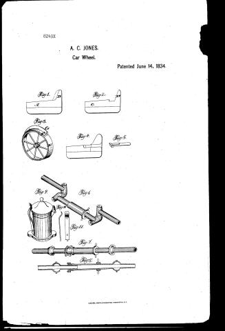
A.C. Jones' Patent Drawing for Improvement in Locomotive engines, Cars, and Carriages used on Railroads

National Archives, Restored Patent Drawings (Record Group 241) · Full-size scan at the National Archives · Catalog record
Show the text on the drawing Hide (88 words)
Words on the drawing as machine-read by the National Archives; not checked. Useful mainly for searching.
Railway Relling Stock, / wheels / 100. / FAILWAYS, / Zire Fasteness / Tire Fasteners, / Caterier / Mountings & Fitting / L123] Wheels. / CLASSI: ICATION / N bar While / $249 X / DIV ISION / 8249 / A. O.Jones / Impt in Locomotive Engines, Cars & Carriages, / used upon Rail Roads. / Patented June 14. 1834. / Fig 1. B / Fig 2. / Claims 1) False flanch- / Fig3. / 2) Flexible fife water / Fig4. / Fig 5. feed to documation - / 3) Spring Catchfor / oil Cup lid- / Fig 6. / Fig 9. / O/A / Fig 10. / Fight / Fig 1. / <00 / Fig8. / 15ml / and / TO
USPTO scan
The patent as scanned by the USPTO
-
 Page 1
-
 Page 2
-
 Page 3
-
 Page 4


U.S. Patent and Trademark Office · Google Patents
Show the transcription Hide (943 words)
Machine transcription (LightOnOCR) of the pages as scanned by the USPTO, most of them the handwritten copies made when the records were restored after the 1836 fire. Not checked; it can misread handwriting, so compare it with the scan.
Page 1.
8249X
A. C. JONES.
Car Wheel.
Patented June 14, 1834.
Fig. 1.
A
B
Fig. 2.
C
D
Fig. 3.
G
Fig. 4.
Fig. 5.
Fig. 9.
Fig. 6
Fig. 10
Fig. 11.
Fig. 7.
Fig. 8.
Page 2.
June 14, 1834
Alfred C. Jones of Philadelphia, Pennsylvania.
Letters Patent
The schedule referred to in these Letters Patent, and making part of the same containing a description in the words of the said Alfred C. Jones himself, of his improvement in Locomotive Engines, Cars, and Carriages used upon Rail Roads.
To all whom it may concern.
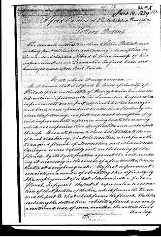
Be it known that I, Alfred C. Jones of the City of Philadelphia in the State of Pennsylvania, have invented certain improvements in Locomotive Engines, which improvements are in part applicable to other carriages and cars, used upon Rail Roads, and I do hereby declare the following, is a full and exact description of my said improvements reference being had to the drawing which accompanies this specification and makes a part thereof. It is well known to those habituated to the use of such machinery, that the iron tire, which forms the tread and flange of Locomotive and other Rail Road Carriages, wears rapidly out, on the bearing of the flange, by its friction against the rail, rendering it necessary in the course of a few months, to renew the tire at a very heavy cost. My first improvement consists in a mode of obviating this difficulty, by the employment of what I denominate a false flange, in figure 1. The part A represents a cross section of that portion of the tire, which forms the tread and the part B, that which forms the flange. The latter, excluding the dotted line, exhibits a flange as worn by a continued use of some months. The dotted lines showing
Page 3.
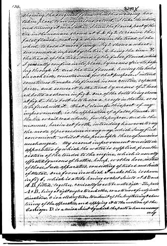
showing the original form when this wearing has taken place to an injurious extent, I take the wheel, and turning it in a lathe, I turn the flanch part of the tire in the manner shown at 6. D. fig 2. to receive the false flanch, making a shoulder in the tread of the wheel, to hold it more firmly. Fig 3. shows a wheel, surrounded in part by the tire, 6. being the rim—T, the tread of the tire, and by the false flanch, which I generally confine in its place, by means of rivets passing through it, and the true flanch, having the holes on each side, countersunk for that purpose. I intend sometimes to make the flanch in one entire, separate piece, and secure it to the tread by means of 3. headed bolts as shown in fig 4. one of the bolts being shown at fig 5. This bolt is to leave a recess in the tire, so as to be flush with it. What I claim for this part of my improvement, is the application of a false flanch, to the tire or railroad wheels; for the purpose, and in the manner, herein set forth, intending however to vary the mode of procedure in any way, which I may find convenient, whilst the principle thereof remains unchanged. My second improvement consists in apparatus by which the water is supplied from the cistern of the tender to the engine, which is usually effected by means of leather, hemp, or other hose, instead of those, I use apparatus, consisting of tubes, and joints of metal, one form in which I make this, is shown in fig 6, which is a tube having socket joints at A B and A' B', fitted, together, conically so as to be watertight. The parts A & B', being at right angles to each other, so as to move freely into directions, C is a sliding tube, to admit of the lengthening & shortening of the apparatus, and applying it to the motion of the Carriage. D. is a union joint by which the parts when necessary may
Page 4.
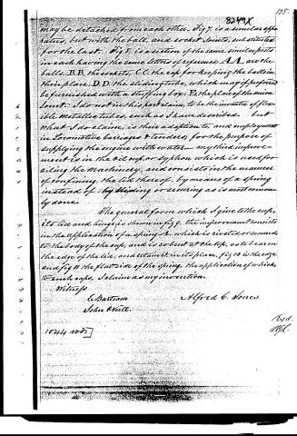
may be detached from each other. Fig 7. is a similar apparatus, but with the ball, and socket joints, substituted for the last. Fig 8. is a section of the same similar parts in each having the same letters of reference A.A. are the balls, B.B. the sockets, C.C. the cap for keeping the balls in their place, D.D. the sliding tube, which may if preferred be furnished with a stuffing box, E.E. the place of the union joints. I do not in this part claim, to be the inventor of flexible metallic tubes, such as I have described, but what I do claim, is their adaptation, and employment in locomotive carriages & tenders, for the purpose of supplying the engine with water. My third improvement is in the oil cup, or siphon which is used for oiling the machinery, and consists in the manner of confining, the lid thereof, by means of a spring instead of by slipping or securing as is most commonly done.
The general form which I give to the cup, its lid and hinge is shown in fig 9. the improvement consists in the application of a spring A. which is riveted or secured to the body of the cup, and is so bent at the top, as to bear on the edge of the lid, and retain it in its place, fig 10 is the edge and fig 11 the flat side of the spring. The application of which, to such cups, I claim as my invention.
Witness
E. Bartman
John Wille.
Alfred C. Jones.
1844 no 85
Expt.
N.Y.C.
Published accounts: journal notice
Notice in the monthly list of patents, with remarks
Journal of the Franklin Institute, new ser., vol. 15 (1835), p. 35 · View the page
19. For improvements in Locomotive Engines, Cars, and Carriages, used upon Rail-roads; Alfred C. Jones, city of Philadelphia, June 14.
Remarks. The improvements claimed under this patent are three in number. The first consists in the application of what is called a false flanch, to obviate the difficulty resulting from the rapid wear of the tire, where the tread and flanch come in contact with the rail. When this has taken place, the wheel is to be turned in a lathe, to adapt it to the receiving of the false flanch, which is to be riveted on, in a manner shown in the drawings. The second relates to the apparatus for supplying water from the cistern of the tender, to the boiler. This consists in the substitution of metallic tubes for the hose commonly used, which tubes have ball and socket joints, or others, admitting of a ready motion in all directions. The patentee says, "I do not in this part claim to be the inventor of flexible metallic tubes, such as I have described; but what I do claim is their adaptation to, and employment in, locomotive carriages and tenders, for the purpose of supplying the engines with water." The third improvement is in the oil cup, or syphon, which is used for oiling the machinery, and consists in the manner of confining the lid thereof by means of a spring, instead of by sliding, or screwing, as is most commonly done. The mode of applying the spring is represented in the drawing, and its application is claimed.
About this record
- Patentee
- DATAMP
- Date
- the Name and Date index of patents, DATAMP, USPTO records
- Invention
- DATAMP
- Listed in
- the Name and Date index of patents, DATAMP, USPTO records, Jim Shaw's X-patent list, the Journal of the Franklin Institute, Burke's List of Patents (1847)
- Burke's 1847 Patent Office list gives the same patent.