

Drawings and documents
National Archives restored drawings: drawing
James Stimpson's Patent Drawing for an Improvement in the Mode of Constructing Rail-road Wheels

National Archives, Restored Patent Drawings (Record Group 241) · Full-size scan at the National Archives · Catalog record
Show the text on the drawing Hide (92 words)
Words on the drawing as machine-read by the National Archives; not checked. Useful mainly for searching.
JAMES STIMPSON'S - IMPROVEMENT IN THE MODE / [123] Wheels. / 11 / whitegrapt / OF CONSTRUCTING RAIL-ROAD WHEELS. / Patented 23ʳᵈ Get, 1834 / CEASSIFICATION / 105. Railway Rolling Stock, / 8466 X / mod / Patented October. 23.1834, / Wheels, Integral, / Cast. / DIVISION / 8466 / Aut Oeen restored / Car-wheels / NAI / N°2. / No / A cross section of the Hub, Spokes and Rim, the spokes extending into the hub, as far as the dolled lines.- / № 2. A Perspec & I've new of the Wheel as Finished, with the Rim shrunk on to the Spokes.-
USPTO scan
The patent as scanned by the USPTO
-
 Page 1
-
 Page 2
-
 Page 3
-
 Page 4
-
 Page 5


U.S. Patent and Trademark Office · Google Patents
Show the transcription Hide (1,412 words)
Machine transcription (LightOnOCR) of the pages as scanned by the USPTO, most of them the handwritten copies made when the records were restored after the 1836 fire. Not checked; it can misread handwriting, so compare it with the scan.
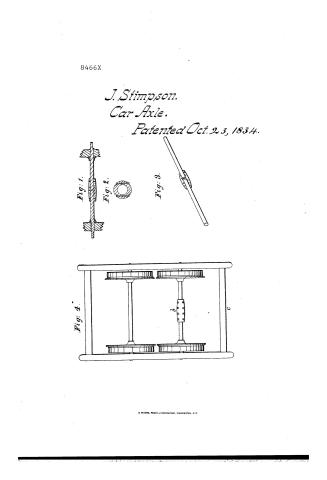
Page 1.
8466X
J. Stimpson.
Car Axle.
Patented Oct. 23, 1834.
Fig. 1.
Fig. 2.
Fig. 3.
Fig. 4.
H. PETERS, PHOTO-LITHOGRAPHER, WASHINGTON, D.C.
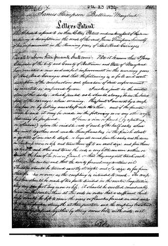
Page 2.
James Simpson Baltimore Maryland
Letters Patent
The Secretary referred to in these Letters Patent and making part of this same containing a description in the words of the said James Simpson himself of his improvement in the running gears of Rail Road Carriages
To all to whom these presents shall come: Be it known that James Simpson of the City and County of Baltimore and State of Maryland have invented a new and useful improvement in the running gears of Rail Road Carriages and that the following is a full and exact description of the construction and operation of said improvement as invented or improved by me. I make a joint in the centre of one of the axles, which jointed axle should always be in the hind part of the carriage when running. This joint I connect by a couple long box or by letting one shaft into the other, and if the former mode be used it may be made in the following or in any other way that may be preferred. I form a rim or flange (by a putting or otherwise) upon the middle ends of each of the half axles where they meet together and make these flanges in the finish about a quarter of an inch deep or larger all round than the axles and the same in thickness more or less and turn them off to an exact size, and face them up to each other and turn the ends a very little so as to within or beneath the base of the rim or flange so that they may not touch each other in the centre and that the cavity formed may contain oil. The axles should be turned exactly straight and of a size as far from the flanges or rims as the coupling is intended to reach. The couple long box should be made of two parts divided in the centre longitudinally say one foot long more or less, it should be worked considerably larger in the centre than at the ends in order that a sufficient thickness should be left to cover the rims or flanges formed on said axles to give it proper strength at their junction and the coupling to be held together by strong screw bolts with nuts, or it.
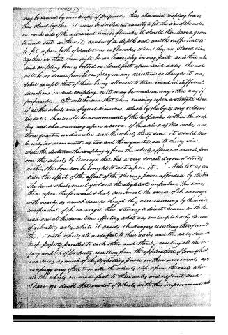
Page 3.
may be secured by iron hoops if preferred. Thus when said coupling box is thus closed together, it may be drilled not exactly to fit the size of the axles on each side of the aforesaid rims or flanches; it should then have a groove turned out within its centre of a depth and width sufficient to fit upon both of said rims or flanches when they are placed along together so that there will be no loose play in any part, and that when said coupling box is bolted or closed fast upon said axles the axle will be as secure from loose play in any direction as though it was solid except that of their being allowed to turn round in different directions in said coupling or it may be made in any other way if preferred. It will be seen that when running upon a straight road if all the wheels were of equal diameters, which by the by is very seldom the case, there would be no movement of the half axles within the coupling and when running upon a curve, if the axle was two inches and three quarters in diameter and the wheels thirty six, it would then be only in movement as two and three quarters are to thirty six, while the distance the coupling is from the wheels affords so much power over the wheels by leverage that but a very small degree of stress within the box can be brought to act upon it. Now let us consider the effect of the effect of the steering power afforded by the iron. The hind wheels must yield to the slightest impulse. The cones then upon the forward wheels can direct the course of the carriage with nearly as much ease as though they were running by themselves independent of the carriage, thus steering a direct course with the road and at the same time effecting what was contemplated by the use of vibrating axles, while it avoids the dangers resulting therefrom & this, with wheels all made fast to their axles and the axles themselves keep perfectly parallel to each other and thereby avoiding all the injury and loss of property resulting from the application of loose wheels and saves as much of the propelling power in their movements as is necessary very often to make the wheels slip upon the rails when all the wheels are made fast to their axles and no joint used. I have no doubt that one set of wheels with this improvement and
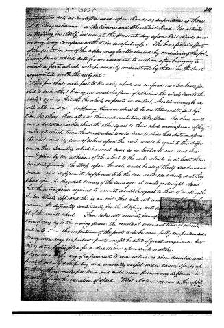
Page 4.
84661
24
outlast two sets as heretofore used upon Roads as serpentine is those of the Chesapeake or Baltimore and Ohio Rail Road. No article so trifling in itself in use at the present day upon Rail Roads can in any way compare with it in usefulness. The beneficial effects of the joints in one of the axles may be illustrated by considering the following points which call for an easement to motion after bringing to mind a fact which will be readily understood by those in the least acquainted with the subject.
Then four wheels made fast to two axles which are confined in close brass plates to each other (bearing in mind the power of adhesion the wheels have to the rails) requires that all the wheels or points in contact, should always be exactly alike in size. Supposing then one wheel to be one thousandths part less than the others then after a thousand revolutions takes place. The three would run a distance greater than the other equal to their whole circumference if they could all which time the small wheel would have to slide that distance upon the rail and its power of action upon the rails would be equal to the difference in their diameters which in most cases is as two to one and that multiplied by the adhesion of the wheel to the rail which is at least three hundred pounds the stress upon the axle would be all of thirty six hundred pounds and suppose it happened to be the case with 100 wheels and they placed upon the diagonal corners of the carriage it would go straight ahead but the extra power required to move it would be equal to that of making the two wheels slip and this is an evil that will not come singly but will increase the difficulty continually for the slipping will not only take up a lot of the small wheel. Then take into view its powerful effect in running a train of cars as to the moving power. The constant wear and tear of wheels and rails &c in the imbalances of the joints will be more fully comprehended. Many more very important points might be cited of great magnitude but this is not a proper place for a dissertation upon such matters.
I have used a very easy way of experiment to some extent as above described and found it entirely satisfactory and eminently useful under various speeds up to thirty three miles per hour and could never perceive any difference in its action from the variation of speed. What I claim as new is the application
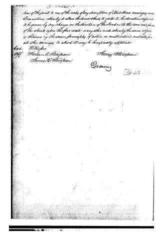
Page 5.
tion of the joint to one of the axles of any description of Rail Road carriages and Locomotives, whereby to allow the hind wheels to yield to the direction required to be given by any change in the direction of the Road or to the conical form of the wheels upon the fore axle: or any other mode whereby the same object is obtained by the same principles of action or construction, and also for all other carriages to which it may be beneficially applied.
Exl. W. Truex
M.C. Julia M. Stimpson
James H. Stimpson
James Stimpson
Drawing
1442
Published accounts: journal notice
Notice in the monthly list of patents, with remarks
Journal of the Franklin Institute, new ser., vol. 15 (1835), p. 329 · View the page
41. For Wheels for Rail-road Cars and Locomotives; James Stimpson, city of Baltimore, October 23.
Remarks. These wheels are to be made wholly of wrought iron, with the exception of the nave, or hub. The spokes are to be equal in width to the rim of the wheel, and they are to have a rib on each side, so that a transverse section of them will be in the form of a t; they are to be made by rolling, and are to be laid in the flask in which the hub is moulded, so that their inner ends shall be embraced by it; their outer ends being so formed as to adapt them to the rim. The tread and flanch forming the exterior of the rim, are to be of the usual shape; upon its interior there are to be two projections, one of which at about the middle part of the rim, may constitute a fillet of half, or five-eighths of, an inch thickness and rise, and the other a flanch, projecting inwards, on the side opposite to that on the tread. These are intended to strengthen the rin, without the necessity of using a large portion of metal. The rims are to be made by rolling, which it is intended to do with such accuracy as to obviate the necessity of turning them. The ends of the spokes, and the interior of the rim, being properly adapted to each other, the latter is to be heated and placed on the former, when, by its contraction in cooling, the two parts will, by means of notches, or recesses, become firmly united, without the necessity of bolts, or screws. The claim is to "the internal flanches, or ribs, within the internal periphery of the rim of the wheel, and the form, and mode, of fitting the spokes, so as to connect them and the rim together without screw-bolts, or rivets." We have no doubt of the possibility of making wheels in the way above pointed out, or of their goodness when made; but we have at present no works for rolling edge rails, for rail-roads, nor are we likely to be able to compete with the English in this manufacture, for some time to come; yet the rolling of them could be more readily accomplished than that of the rims in question; we apprehend, therefore, that there is but little prospect of seeing the foregoing plan experimentally tested, on this side of the Atlantic, in time to reward the inventor, and to repay the expense of his labour.
About this record
- Patentee
- DATAMP
- Date
- the Name and Date index of patents, DATAMP, USPTO records
- Invention
- DATAMP
- Listed in
- the Name and Date index of patents, DATAMP, USPTO records, Jim Shaw's X-patent list, the Journal of the Franklin Institute, Burke's List of Patents (1847)
- Burke's 1847 Patent Office list gives the same patent.