

Drawings and documents
USPTO scan
The patent as scanned by the USPTO
-
 Page 1
-
 Page 2
-
 Page 3
-
 Page 4
-
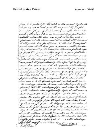 Page 5


U.S. Patent and Trademark Office · Google Patents
Show the transcription Hide (1,462 words)
Machine transcription (LightOnOCR) of the pages as scanned by the USPTO, most of them the handwritten copies made when the records were restored after the 1836 fire. Not checked; it can misread handwriting, so compare it with the scan.
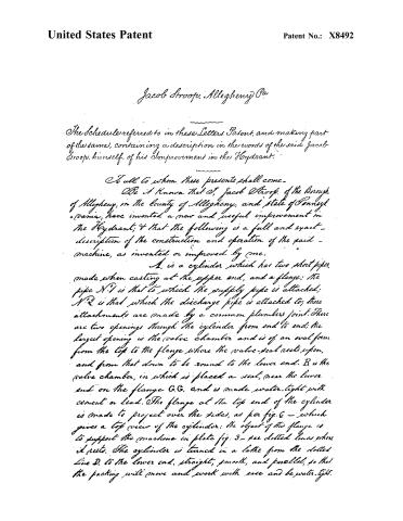
Page 2.
United States Patent
Patent No.: X8492
Jacob Stroop, Allegheny Pa
The Schedule referred to in these Letters Patent, and making part of the same, containing a description in the words of the said Jacob Stroop, himself, of his Improvement in the Hydrant.
To all to whom these presents shall come—
Be it known that I, Jacob Stroop, of the Borough of Allegheny, in the County of Allegheny, and State of Pennsylvania, have invented a new and useful improvement in the Hydrant; and that the following is a full and exact description of the construction and operation of the said machine, as invented or improved by me.
A. is a cylinder which has two short pipes, made when casting at the upper end, and a flange; the pipe N°1 is that to which the supply pipe is attached; N°2 is that which the discharge pipe is attached to; these attachments are made by a common plumbers joint. There are two openings through the cylinder from end to end; the largest opening is the valve chamber and is of an oval form from the top to the flange where the valve-seat rests upon, and from that down to be round to the lower end. B is the valve chamber, in which is placed a seat, near the lower end on the flange G.G. and is made water-tight with cement or lead. The flange at the top end of the cylinder is made to project over the sides, as per fig. 2 — which gives a top view of the cylinder; the object of this flange is to support the machine in plate fig. 3 — see dotted lines where it rests. The cylinder is turned in a lathe from the dotted line D. to the lower end, straight, smooth, and parallel, so that the packing will move and work with ease and be water-tight.
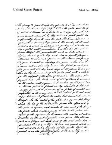
Page 3.
United States Patent
Patent No.: X8492
The opening E, passes through the cylinder, to N.2, admits the water into the discharge pipe. F.F. is the valve seat the top of which is turned in a lathe to a V. edge upon which the valve H, rests when shut. The valve is a small metal box sufficiently large to cover the seat. The lower side is made open with a small flange round the inside, at the mouth, which is to assist in holding the packings in the box. The box is filled with gum-elastica. I is the valve stem which passes through the gum-elastica and a hole which is left in centre of the box, and has a small flange attached to it which presses on the lower surface of the gum & assists in holding the gum in the box. J is a screw cut on the rod and a bar fitted so as to press the gum into the box and keep it to place. K is a guide bar in the lower end of the valve seat, with a hole for the support of the stem of the valve. The valve stem projects below the lower end of the cylinder B, as much as the valve will require to be raised off the seat. L is a strainer which is placed in the chamber B below the supply pipe which is made of a plate of metal and perforated with many small holes which will not admit any substance to pass to the valve that cannot be admitted through. In the centre of the plate is a square hole through which the top of the valve stem passes. The upper end of the stem is square, and made to rise and fall through the plate, which makes a guide to the valve stem. The object of the square is to cause the valve at all times to settle on the seat in position and place. This strainer rests on a flange at each end of the oval chamber, as per dotted lines 4-4 in Fig. C. M is an air vessel which covers and closes the valve chamber at top, water-tight. This vessel is in the form of a globe with a cavity in the
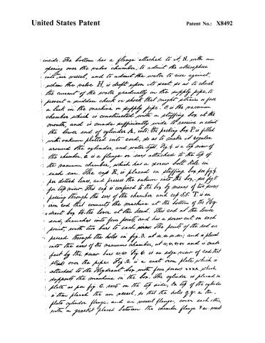
Page 4.
United States Patent
Patent No.: X8492
inside. The bottom has a flange attached to it, N, with an opening over the valve chamber, to admit the atmosphere into air vessel, and to admit the water to rise against, when the valve H, is dropped upon its seat, so as to check the current of the water gradually in the supply pipe, to prevent a sudden check or shock that might strain or force a leak in the machine or supply pipe. O is the vacuum chamber which is constructed with a stuffing box at the mouth, and is made sufficiently wide to receive or admit the lower end of cylinder A, into the packing box P, is filled with oakum platted into cord, so as to make it regular around the cylinder, and water-tight. Fig. 4 is a top view of the chamber, a is a flange or ears attached to the top of the vacuum chamber, which has a screw bolt hole in each ear. The cap R, is placed on stuffing box see fig. 4, for dotted lines, and presses the oakum into the box, see fig. 5 for top view. This cap is confined to the box by means of two screws passing through the ears of the chamber and cap S.S. T is an iron rod that connects the machine at the bottom of the Hydrant box to the lever at the head. This rod at the lower end, branches into four points, and has a screw cut on each point, with two bars to each screw. The points of the rod are passed through the holes in fig. 3, at u, u, u, u; and is placed into the ears of the vacuum chamber, at v, v, v, v, and is made fast by the screw bars w, w. Fig. 6 is an edge view of rod that stands over the pipes. Fig. 8 is a cast iron plate which is attached to the Hydrant box with four screws x x x x, which supports the machine in the box. The cylinder is placed in plate as per fig. 6, rests on the top side, on top of the cylinder is then placed the air vessel, so that the holes y, y, in the plate cylinder flange, and air vessel flange, cover each other, with a gasket placed between the chamber flange & air vessel
Page 5.
United States Patent
Patent No.: X8492
flange to be water-tight. The whole is then screwed together with two screws, one on each side the air vessel. Fig 7 is flat view of the flange of the air vessel, - a a, the lever at the head of the box - b b, is an accommodating joint which vibrates when the lever a a is put in motion and is fastened at the lower end to a knob that is screwed to the guide bar for the rod T. The rod T, and joint is connected to the lever pins or screw c c... is the wooden box which contains the machine. There is no particular size or proportion given, as there may be, in some particular cases, a variation necessary, but in the common use of Hydrants the drawing hereunto annexed will answer as a scale to proportion by. The object of the foregoing described machine is to be applied to the drawing water from supply pipes or conductors for water under ground for the purpose of supplying families in town & cities &c. and those Hydrants are for family purposes. When water is required to be drawn, the lever a a is to be raised upwards, which will cause the receiving chamber to rise and discharge the water from it, into the discharge pipe, and when the bottom of that chamber rises sufficiently high, it will come in contact with the lower end of the valve stem, and raise the valve off its seat, so as to pass off the water from the supply pipe through the machine, & out of the discharge pipe. In stopping the machine the lever is brought down, which will admit the valve to drop to its seat and cut off the water, and as the chamber will continue to sink, the water in the discharge pipe will follow & be lodged in the chamber below the supply pipe some inches, and . . . . . . . . . the discharge pipe left empty.
Witnesses
Henry Reelin
Jacob Stroop
1800
Published accounts: journal notice
Notice in the monthly list of patents, with remarks
Journal of the Franklin Institute, new ser., vol. 15 (1835), p. 393 · View the page
13. For an improvement in the Hydrant; Jacob Stroop, Allegheny, Allegheny county, Pennsylvania, November 11.
Remarks. The main object to be accomplished by the machinery here patented, is not expressed either in the petition or the specification; this object is, however, to withdraw the water from the discharge pipe in hydrants, so as to prevent its freezing. In vol. xiii., p. 405, we have given the specification of a patent for a similar machine, obtained by Messrs. Laning and Newton, on the 30th of July, 1833; and at p. 392 we have noticed one granted to Mr. Stroop, on the 16th of December of that year, for a contrivance exactly resembling it in principle. In the patent before us, he has VOL. XV. No. 6. -JUNE, 1835. 50 given another modification of the same thing, without, however, alluding to his former patent, or pointing out the improvements claimed in the present; in fact, there is not any claim appended to it. For the general principle of action, we refer to Laning & Newton's specification. So far as dates are concerned, the presumption is that they were the first inventors, and the variations introduced by Mr. Stroop do not, certainly, constitute his a new machine.
About this record
- Patentee
- the Journal of the Franklin Institute, Journal
- Date
- the Name and Date index of patents, USPTO records, Jim Shaw's X-patent list
- Invention
- the Name and Date index of patents
- Listed in
- the Name and Date index of patents, USPTO records, Jim Shaw's X-patent list, the Journal of the Franklin Institute, Burke's List of Patents (1847)
- The patentee's full name comes from the Franklin Institute's journal.
- Burke's 1847 Patent Office list gives the same patent.