

Drawings and documents
USPTO scan
The patent as scanned by the USPTO
-
 Page 1
-
 Page 2
-
 Page 3
-
 Page 4


U.S. Patent and Trademark Office · Google Patents
Show the transcription Hide (658 words)
Machine transcription (LightOnOCR) of the pages as scanned by the USPTO, most of them the handwritten copies made when the records were restored after the 1836 fire. Not checked; it can misread handwriting, so compare it with the scan.
Page 1.
8736½X
J. Denkyne.
Straw Cutter.
No Printed Specification Available
Patented Apr. 2, 1835.
Page 2.
8736547
April 2, 1835
John D. D.
Letters Patent
April 2, 1835
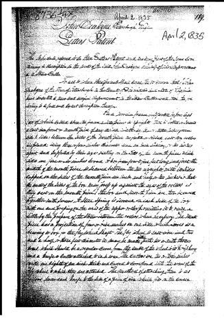
The Schedule, referred to in these Letters Patent and having part of the same containing a description in the words of the said John D. D. himself of his improvement in a Straw Cutter.
To all to whom these presents shall come, Greeting: Know ye that I, John D. D., of the Town of [illegible] in the County of [illegible] and State of Virginia, have invented a new and useful improvement in the Straw Cutter, and for the same being to be fully and clearly described hereafter.
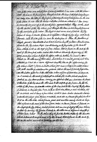
The said Straw Cutter comprises a frame of which is set at an angle to the frame of the piece in right angle. There is a set of two or more front or mouth piece of any kind, such as the common straw cutter, which is placed between the sides of the mouth piece and the roller, and the roller is placed. Being three or four inches diameter, and so in its manner, it is supported and supported by their respective sides of the mouth piece, which sides are five or six inches broad and from four to five feet long, just at the middle of the mouth piece, is secured between the two uprights, with its sides capped on the sides of the mouth piece, and such as the sides, that the ends of the sides of the box, being only up against the ends of the rollers, so they rest on the mouth piece; the box and mouth piece are then secured together with screws. A steel spring is secured on each side of the box with one end springing on the axis of the upper roller permitting it to move a little by the pressure of the straw between the rollers when necessary. The Mouth Piece has a projection of four or five inches on one side, which serves as a hearing or box for the fly wheel shaft. The fly wheel is cast iron and two and a half or three feet diameter. It may be made with two or with three arms, which should be a regular curve from the centre of the wheel to the top, and a knife or cutter attached to each arm. The cutters are two or three inches wide, eight or ten inches thick and curved to correspond with the arms of the fly wheel to which they are attached. The method of attaching them is as follows: Secure each knife to the side of a piece of iron which fits on the arms.
Page 4.
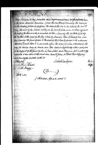
What I claim as my invention and improvement and not previously known is the same described machine and first the method of having the knives for the feeding rollers by capping the sides of the top and the sides of the bottom given the use of the rollers resting on the bottom piece and working against the under side thereof, as described herein. Secondly, the method of fixing the cutter to the arms of the fly wheel by attaching them to pieces of iron and then securing the pieces of iron to the arms of the wheel by screws or in a manner that will permit them to be movable upon the arms for when attached in this way the knives may be made very thin and of sufficiently strong and firm to the support of the pieces of iron in their sides, and they can also be accurately adjusted and set close to the cast iron wheel piece without their slipping and coming in contact with it.
Witness:
G. J. Thomas
A. Brady
John Blackyne
(2)
(Patented April 2, 1835)
About this record
- Date
- USPTO records
- Listed in
- USPTO records
- This patent does not appear in the Name and Date index.