

Drawings and documents
National Archives restored drawings: drawing
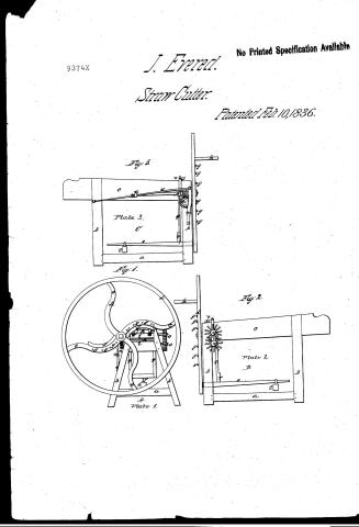
J. Evered's Patent Drawing for a Machine for Cutting Straw

National Archives, Restored Patent Drawings (Record Group 241) · Full-size scan at the National Archives · Catalog record
Show the text on the drawing Hide (45 words)
Words on the drawing as machine-read by the National Archives; not checked. Useful mainly for searching.
119. CARE OF LIVE STOCK. / Straw Cutters. / Rotary Wheel. / Roller or Apron Feed. / 12 how tuller / Findered. / againts / JEVERED'S / Machine for Cutting / Patented / retart / 93744 / 9374 X / Plate 3. / 84 / Plate 2. / BF / Plate z,
USPTO scan
The patent as scanned by the USPTO
-
 Page 1
-
 Page 2
-
 Page 3
-
 Page 4


U.S. Patent and Trademark Office · Google Patents
Show the transcription Hide (1,043 words)
Machine transcription (LightOnOCR) of the pages as scanned by the USPTO, most of them the handwritten copies made when the records were restored after the 1836 fire. Not checked; it can misread handwriting, so compare it with the scan.
Page 1.
9374X
J. Evered.
Straw Cutter.
Patented Feb. 10, 1836.
No Printed Specification Available
Fig. 3
Plate 3.
Fig. 1.
Plate 1.
Fig. 2.
Plate 2.
Page 2.
Feb. 10, 1836 9374X 229.
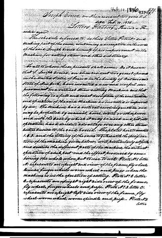
Joseph Grier, an alien resident two years U.S.
date Feb. 10, 1836
Letters Patent, Revised & Re-
corded again
The schedule referred to in these Letters Patent and heretofore part of the same, containing a description in the words of the said Joseph Grier himself of his improvement in the Machine for cutting straw and other substances.
To all to whom these presents shall come: Be it known that I, Joseph Grier, an alien resident two years U.S. in the United States, of being in the county of Ontario and State of New York, have invented a new and useful improvement in a vertical straw cutting Machine and that the following is a full and exact description of the construction and operation of the said Machine as invented or improved by me: The Machine has a vertical revolving motion and may be propelled by manual, horse, water or other power and with the ease by which it may be used and put into operation, has a decided advantage over any other straw cutter known to the said Grier. The plates heretofore 1. U.S. and the lettering of the same together with the specification of the Machine given below, will particularly set forth and describe the different parts of the Machine, the distinct operation of each part and the effect produced by combining the whole when put to use to wit: Plate A. Letter A. represents an upright back view of the frame, fly wheel, knives, finger wheels, worm wheel and pegs when the Machine is in the operation of cutting. Plate A. Letter B. represents an upright right side view of the frame, fly wheel, finger wheels and pegs. Plate A. Letter C. represents an upright left side view of the frame, fly wheel, worm wheel, worm spindle and pegs. Plate A. Letter
Page 3.
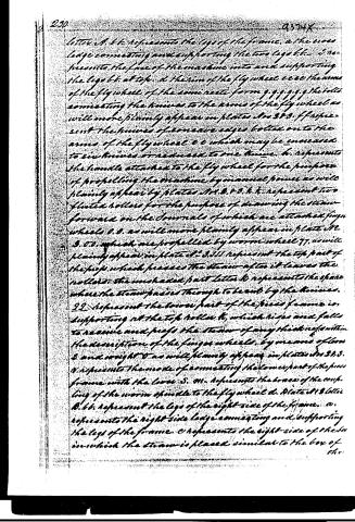
letter A. b. represents the legs of the frame. a the cross large connecting and supporting the two legs b. b. I represent the face of the machine into and supporting the legs b. b. at top. a the rim of the fly wheel c c c the arms of the fly wheel of the same recti form g g g g g g the bolts connecting the knives to the arms of the fly wheel as will more plainly appear in plates Nos 3 & 3. f f f represent the knives of concave edges bolted on to the arms of the fly wheel c c which may be increased to six knives or reduced to one knife. h. represents the handle attached to the fly wheel for the purpose of propelling the machine by manual power as will plainly appear by plates Nos 3 & 3. h. h. represent two fluted rollers for the purpose of drawing the steam forward on the journals of which are attached finger wheels d. d. as will more plainly appear in plate No 3. d. d. which are propelled by worm wheel 77, as will plainly appear in plate No 3. d. d. I represent the top part of the pipe which passes the steam after it leaves the rollers. the unshaded part letter k represents the space where the steam passes through to be cut by the knives. 22. represents the lower part of the press frame in supporting at the top roller k, which rises and falls to receive and press the steam of any thickness within the description of the finger wheels, by means of lever 3 and weight 6 as will plainly appear in plates Nos 3 & 3. v. represents the mode of connecting the lower part of the press frame with the lower 3. m. represents the boxes of the coupling of the worm spindle to the fly wheel d. Plate 4. letter A. b. b. represents the legs of the right side of the frame. a. represents the right side large connecting and supporting the legs of the frame. c represents the right side of the box in which the steam is placed similar to the box of the
Page 4.
The common straw cutter, d represents the upright axis of the flywheel, gggggg represents the bolts fastening the knives to the arms cc, as described in plate 1. k represents the handle by which the flywheel is propelled by manual power. oo, represents the double fingerwheels which may rise and fall, from the center, from one inch to a foot if required and still much perfectly smooth. Annulars of which are placed the rollers bb, as described in plate 2. 1 which rollers will rise and fall to admit straw or any other fodder of any thickness within the description of the fingerwheels, the top roller being pressed by the levers, and weight g, attached by the lower part of the press frame g & f. w represents the screw nut to support the brace x. Plate 2. 3, letter c, represents an upright left view of the machine. b.b. a.b. gggggg. d. b.s.t.g. represent the same as described in plate 1. 3. 3. represents the worm and spindle meshing into the axis of worm wheel bb on which is placed the flywheel d which acts the rollers, knives and all in motion. a represents the center screw to the spindle D by which the knives may be drawn close to and regulated with the face of the machine. X represents a brace supporting the coupling of the spindle D and the center screw W. w. the screw nut to support the brace x. on the coupling for the annular of spindle D.
The petitioner claims an exclusive right to the invention of the fingerwheels, the rising and falling of the rollers, the compression produced by the levers, D and weight t, the concavity of the knives, axis, the plan of the face of the machine through which the straw is drawn, the center screw on the worm and spindle and its use.
Witnesses
Samuel D. Buckingham
William Burke
Joseph Green
Filed 1851
Published accounts: journal notice
Notice in the monthly list of patents, with remarks
Journal of the Franklin Institute, new ser., vol. 18 (1836), p. 189 · View the page
The claim is to the mode of producing motion by the action of the cogs. 36. For a Machine for Cutting Strau; Joseph Evered, an alien, who has resided two years in the United States, February 10.
Remarks. The description of this machine refers to the drawing throughout, and ends with a claim to "the finger wheels; the rising and falling of the rollers; the compression produced by the lever and weight; the concavity of the knives edges; the plan of the face of the wheel through which the straw is drawn; the centre screw on the worm and spindle, and its rise." The general form of the machine is such as has been in use for more than half a century, the straw being contained in a trough, furnished with fluted feeding rollers, and the cutting effected by curved knives on the arms of a fly wheel, revolving at one end of the box; these curved knives, it will be seen, are claimed as new; if the inventor could go back as far as we can in the recollection of the use of curved knives, in a manner precisely the same with their employment in this machine, he would not place himself among the novelties of the day. There are other things claimed, which are in the same predicament, and where so many individual things are particularized, it is not easy to avoid such an error, as few persons are fully informed of what has previously been done in those cases where machines have been long employed, as in cutting straw.
About this record
- Patentee
- DATAMP, Burke's List of Patents (1847)
- Date
- the Name and Date index of patents, DATAMP, USPTO records
- Invention
- DATAMP
- Listed in
- the Name and Date index of patents, DATAMP, USPTO records, Jim Shaw's X-patent list, the Journal of the Franklin Institute, Burke's List of Patents (1847)
- The name conflict was settled by Burke's 1847 list.
- The National Archives' catalog gives the name differently.
- Burke's 1847 Patent Office list gives the same patent.