

Drawings and documents
National Archives restored drawings: drawing
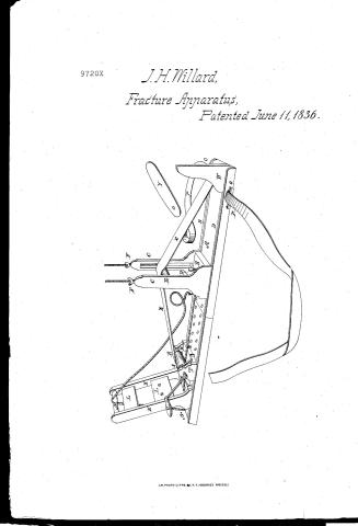
J.H Willard's Patent Drawing for an Apparatus for Setting Broken Bones

National Archives, Restored Patent Drawings (Record Group 241) · Full-size scan at the National Archives · Catalog record
Show the text on the drawing Hide (37 words)
Words on the drawing as machine-read by the National Archives; not checked. Useful mainly for searching.
3. ARTIFICIAL LIMES. / [156] Fracturo Apparatus Apley Suy / IO ATION / #1 / 9720 x / J. H. WILLARDS / 9720X / Apparatus for setting Broken Bones. / Patented June 11th 1836.
USPTO scan
The patent as scanned by the USPTO
-
 Page 1
-
 Page 2
-
 Page 3
-
 Page 4


U.S. Patent and Trademark Office · Google Patents
Show the transcription Hide (1,015 words)
Machine transcription (LightOnOCR) of the pages as scanned by the USPTO, most of them the handwritten copies made when the records were restored after the 1836 fire. Not checked; it can misread handwriting, so compare it with the scan.
Page 1.
9720X
J.H. Willard,
Fracture Apparatus,
Patented June 11, 1836.

A.M. PHOTO-LITHO. N.Y. (OSBORNE'S PROCESS.)
Page 2.
(6) 11/1836 9720X
an 12
Pat. June 11, 1836 545
James H. Willard
Letters Patent
The Schedule referred to in these Letters Patent and making part of the same containing a description in the words of the said James H. Willard himself of his improvement in the apparatus for setting the bones of fractured limbs.
Be it known that I James H. Willard of Brownstown in the County of Sorein and State of Ohio have invented a new and useful improvement being an apparatus for setting the bones of fractured limbs which invention is described as follows reference being had to the accompanying draught. Said apparatus consists of a board A of suitable length and breadth having two grooves D D running the entire length of the board A for the reception of slides and a joint near the center. 1st A slide B with two erect standards C C having a groove in each through which passes long metallic screws attached at their lower extremity to a crossbar E with thumb-nuts F F resting upon the upper extremity of the grooves pieces C C at the bottom of slide B is a thumb screw D. 2nd A slide Q with a roller R a way wheel S a dog T and a crank U. 3rd a slide V with two oblique standards K K two flat crossbars L L the lower one having two perforations and there is a roller M at the top of the standards K K. 4th a slide W called a scotch. At the upper end of board A and on the under side is attached a broad strip of webbing X which passes over the cross bar E on the slide B, and is attached to the roller R in slide Q. At the lower extremity of A is a pulley N. At the upper end of the board on both sides are two staples O O through which passes a strap P Y thin broad splint. In the application of this apparatus the splains entire new grooves. In the first place the grooves (of the board) are kept from the apparatus thereby preventing
Page 3.
546.
ing the necessity, of any counter extending force. In the second place the flexor and extensor muscles are balanced or antagonized by keeping the limb in a flexed or bent position. In the third place the extension is made directly in the axis of the broken bones the apparatus common as the whole limb. It supersedes the necessity of tight lacing, and prevents all evocations from unequal pressure. It admits of the limb being dressed without a possibility of moving or misplacing the bones, which makes it of great importance in all compound fractures. It prevents the contraction of the muscles and consequent misplacing of the bones by keeping up a general and permanent extension thereby procuring the greatest possible degree of safety and convenience. The apparatus places the limb in a situation the most favorable for a free circulation of air around it in every direction. To apply the apparatus in case of fractured femur, a bandage called a roller should be attached to the webbing at its upper extremity. The cramp bar in slide B, should be brought by means of the screws to such a point of elevation as the length of limb requires. The slide A should then be placed at such a distance from the knee as to permit the heel to just drop over the roller D. The webbing should now be made tight. The slide B must be placed a little short of the length of the lower thigh. The slide N should be placed in that groove which will correspond with the inside of the fractured thigh brought down to the slide B, and then left. The operator will then tie a handkerchief or belt above the condyles of the knee, and give the limb into the hands of an assistant in a flexed position, and then assistant will slide the apparatus under the limb and carry it up so as to till the upper extremity of the apparatus rests firmly upon the tuberosity of the Ischium. The cramp or slide N should now be brought up on the groin and firmly secured against the pubis and secured by the pin. If the limb should then be placed
Page 4.
6/11/1836 9720X
547
placed upon the rubbing taking care that the hollow of the ham rests directly over the orifice bar B. The limb will now be fastened to the orifice bar by means of the strap or filler. Such extension should then be made as is necessary to bring the bones in proper position and the slide B. fastened by the thumb screw. An assistant will now be directed to clamp the limb with both hands and draw the muscles from above downwards as in the manner of applying a slings after amputation. While the operator brings the bandage after his hands, till he comes to the knee including the rubbing, when he should turn the bandage once or twice over the knee and under the orifice bar in the form of a figure 8 then apply the splint X on the top of the thigh and carry his roller back to the starting place. Additional extension can be made at discretion by attaching the cord of pulley M. to the projecting extremity of splint X. and letting it run over the roller M. in slide U. That I claim as my invention and which I desire to secure by Letters Patent consists in the apparatus for setting and securing the bones of fractured limbs as before specified and described.
Witnesses
Wm. P. Elliot
Edmond S. Coote
James H. Wallace
996 rts
(Patented 11 June 1836)
Drawing
C. 4
Chf.
Published accounts: journal notice
Notice in the monthly list of patents
Journal of the Franklin Institute, new ser., vol. 18 (1836), p. 215 · View the page
407. Setting bones, apparatus.-James H. Willard, Brownhelm, Ohio,
Published accounts: journal notice
Notice in the monthly list of patents
Journal of the Franklin Institute, new ser., vol. 18 (1836), p. 287 · View the page
502. Saw mill.-Simon Willard, N. Y.
About this record
- Patentee
- DATAMP
- Date
- the Name and Date index of patents, DATAMP, USPTO records
- Invention
- DATAMP
- Listed in
- the Name and Date index of patents, DATAMP, USPTO records, Jim Shaw's X-patent list, the Journal of the Franklin Institute, Burke's List of Patents (1847)
- Burke's 1847 Patent Office list gives the same patent.